ASRock ConRoe1333-1394 driver and firmware
Drivers and firmware downloads for this ASRock item
Related ASRock ConRoe1333-1394 Manual Pages
Download the free PDF manual for ASRock ConRoe1333-1394 and other ASRock manuals at ManualOwl.com
User Manual - Page 3
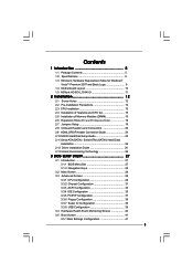
...13 2.4 Installation of Heatsink and CPU fan 15 2.5 Installation of Memory Modules (DIMM 16 2.6 Expansion Slots (PCI and PCI Express Slots 18 2.7 Jumpers Setup 19 2.8 Onboard Headers and Connectors 20 2.9 HDMI_SPDIF Header Connection Guide 24 2.10 SATAII Hard Disk Setup Guide 25 2.11 Serial ATA (SATA) / Serial ATAII (SATAII) Hard Disks
Installation 26 2.12 Driver Installation Guide 26 2.13...
User Manual - Page 4
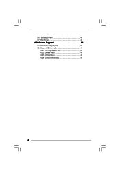
3.6 Security Screen 42 3.7 Exit Screen 43
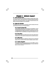
4 Software Support 44
4.1 Install Operating System 44 4.2 Support CD Information 44
4.2.1 Running Support CD 44 4.2.2 Drivers Menu 44 4.2.3 Utilities Menu 44 4.2.4 Contact Information 44
4
User Manual - Page 5
...www.asrock.com
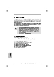
1.1 Package Contents
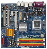
ASRock ConRoe1333-1394 Motherboard (Micro ATX Form Factor: 9.6-in x 9.6-in, 24.4 cm x 24.4 cm)
ASRock ConRoe1333-1394 Quick Installation Guide ASRock ConRoe1333-1394 Support CD One 80-conductor Ultra ATA 66/100 IDE Ribbon Cable One Ribbon Cable for a 3.5-in Floppy Drive One Serial ATA (SATA) Data Cable (Optional) One Serial ATA (SATA) HDD Power Cable (Optional...
User Manual - Page 7
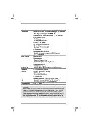
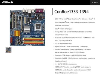
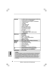
... RAID and "Hot Plug" functions) (see CAUTION 11)
- 1 x ATA100 IDE connector (supports 2 x IDE devices) - 1 x Floppy connector - 1 x IR header - 1 x HDMI_SPDIF header - 1 x IEEE 1394 header - CPU/Chassis FAN connector - 20 pin ATX power connector - 4 pin 12V power connector - CD in header - Front panel audio connector - 2 x USB 2.0 headers (support 4 USB 2.0 ports)
(see CAUTION 12) - 4Mb AMI BIOS...
User Manual - Page 8
... 11 for
proper connection.
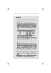
11. Before installing SATAII hard disk to SATAII connector, please read the "SATAII
Hard Disk Setup Guide" on page 25 to adjust your SATAII hard disk drive to
SATAII mode. You can also connect SATA hard disk to SATAII connector
directly.
12. Power Management for USB 2.0 works fine under Microsoft® Windows®
VistaTM 64-bit / VistaTM / XP...
User Manual - Page 9
... Logo
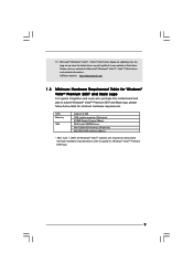
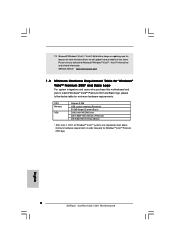
For system integrators and users who purchase this motherboard and plan to submit Windows® VistaTM Premium 2007 and Basic logo, please follow below table for minimum hardware requirements.
CPU Memory
VGA
Celeron D 326 1GB system memory (Premium) 512MB Single Channel (Basic) DX9.0 with WDDM Driver with 128bit VGA memory (Premium) with 64bit VGA memory (Basic)
* After June 1, 2007, all...
User Manual - Page 22
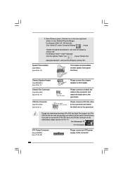
... ground pin.
Though this motherboard provides 4-Pin CPU fan (Quiet Fan) support, the 3-Pin CPU fan still can work successfully even without the fan speed control function. If you plan to connect the 3-Pin CPU fan to the CPU fan connector on this motherboard, please connect it to Pin 1-3.
Pin 1-3 Connected
3-Pin Fan Installation
ATX Power Connector
(20-pin ATXPWR1...
User Manual - Page 24
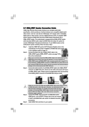
... set-top box, DVD player, A/V receiver and a compatible digital audio or video monitor, such as a digital television (DTV). A complete HDMI system requires a HDMI VGA card and a HDMI ready motherboard with a HDMI_SPDIF header. This motherboard is equipped with a HDMI_SPDIF header, which provides SPDIF audio output to HDMI VGA card, allows the system to connect HDMI Digital TV/projector/LCD devices...
User Manual - Page 25
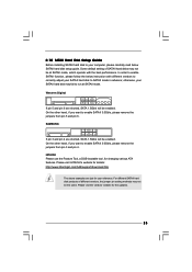
... Hard Disk Setup Guide
Before installing SATAII hard disk to your computer, please carefully read below SATAII hard disk setup guide. Some default setting of SATAII hard disks may not be at SATAII mode, which operate with the best performance. In order to enable SATAII function, please follow the below instruction with different vendors to correctly adjust your SATAII hard disk to SATAII...
User Manual - Page 26
... bridge chipset that supports Serial ATA (SATA) / Serial ATAII (SATAII) hard disks. You may install SATA / SATAII hard disks on this motherboard for internal storage devices. This section will guide you to install the SATA / SATAII hard disks.
STEP 1: Install the SATA / SATAII hard disks into the drive bays of your chassis. STEP 2: Connect the SATA power cable to the SATA / SATAII hard disk. STEP...
User Manual - Page 27
...on.
Because the BIOS software is constantly being updated, the following BIOS setup screens and descriptions ...set up the advanced BIOS features
PCIPnP
To set up the PCI features
Boot
To set up the default system device to locate and load the
Operating System
Security
To set up the security features
Chipset
To set up the chipset features
Exit
To exit the current screen or the BIOS SETUP...
User Manual - Page 30
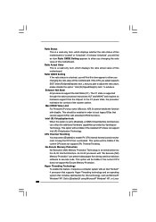
... be hidden if the current CPU does not support No-Excute Memory Protection.
Hyper Threading Technology To enable this feature, it requires a computer system with an Intel Pentium® 4 processor that supports Hyper-Threading technology and an operating system that includes optimization for this technology, such as Microsoft® Windows® XP. Set to [Enabled] if using Microsoft...
User Manual - Page 31
...issue with some power supplies. Please set this item to [Disable] if above issue occurs.
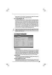
3.3.2 Chipset Configuration
BIOS SETUP UTILITY Advanced
Chipset Configuration
DRAM Frequency
[Auto]
Flexibility Option
[Disabled]
Configure DRAM Timing by SPD [Enabled]
DRAM CAS# Latency
[Auto]
Primary Graphics Adapter
OnBoard HD Audio Front Panel CD-In
OnBoard Lan OnBoard 1394
PCI Fix Function
VCCM...
User Manual - Page 35
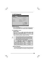
... set to [IDE 1, SATA 2, SATA 4], then SATAII_1, SATAII_3 will not work.
Because Intel® ICH7 south bridge only supports four IDE devices under legacy OS (Windows NT), you have to choose [SATA 1, SATA 2, SATA 3, SATA 4], [SATA 1, SATA 3, IDE 1], or [IDE 1, SATA 2, SATA 4] when the installed device is used with legacy OS.
[SATA 1, SATA 2, SATA 3, SATA 4]
[SATA 1, SATA 3, IDE 1]
[IDE 1, SATA...
User Manual - Page 44
...-ROM drive. The CD automatically displays the Main Menu if "AUTORUN" is enabled in your computer. If the Main Menu did not appear automatically, locate and double click on the file "ASSETUP.EXE" from the BIN folder in the Support CD to display the menus.
4.2.2 Drivers Menu The Drivers Menu shows the available devices drivers if the system detects installed devices. Please install...
Quick Installation Guide - Page 4
... 24.4 cm x 24.4 cm)
ASRock ConRoe1333-1394 Quick Installation Guide ASRock ConRoe1333-1394 Support CD One 80-conductor Ultra ATA 66/100 IDE Ribbon Cable One Ribbon Cable for a 3.5-in Floppy Drive One Serial ATA (SATA) Data Cable (Optional) One Serial ATA (SATA) HDD Power Cable (Optional) One ASRock HD 8CH_1394 I/O Shield One HDMI_SPDIF Cable (Optional)
4 ASRock ConRoe1333-1394 Motherboard
English
Quick Installation Guide - Page 6
... RAID and "Hot Plug" functions) (see CAUTION 11)
- 1 x ATA100 IDE connector (supports 2 x IDE devices) - 1 x Floppy connector - 1 x IR header - 1 x HDMI_SPDIF header - 1 x IEEE 1394 header - CPU/Chassis FAN connector - 20 pin ATX power connector - 4 pin 12V power connector - CD in header - Front panel audio connector - 2 x USB 2.0 headers (support 4 USB 2.0 ports)
(see CAUTION 12) - 4Mb AMI BIOS...
Quick Installation Guide - Page 8
...
CPU Memory
VGA
Celeron D 326 1GB system memory (Premium) 512MB Single Channel (Basic) DX9.0 with WDDM Driver with 128bit VGA memory (Premium) with 64bit VGA memory (Basic)
* After June 1, 2007, all Windows® VistaTM systems are required to meet above minimum hardware requirements in order to qualify for Windows® VistaTM Premium 2007 logo.
English
8 ASRock ConRoe1333-1394 Motherboard
Quick Installation Guide - Page 21
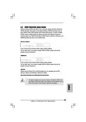
..., for changing various ATA features. Please visit HITACHI's website for details: http://www.hitachigst.com/hdd/support/download.htm
The above examples are just for your reference. For different SATAII hard disk products of different vendors, the jumper pin setting methods may not be the same. Please visit the vendors' website for the updates.
21 ASRock ConRoe1333-1394 Motherboard
English
Quick Installation Guide - Page 23
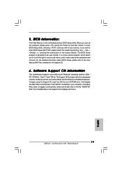
... using the Support CD, insert the CD into your CD-ROM drive. It will display the Main Menu automatically if "AUTORUN" is enabled in your computer. If the Main Menu does not appear automatically, locate and double-click on the file "ASSETUP. EXE" from the BIN folder in the Support CD to display the menus.
23 ASRock ConRoe1333-1394 Motherboard
English