ASRock G PRO driver and firmware
Related ASRock G PRO Manual Pages
Download the free PDF manual for ASRock G PRO and other ASRock manuals at ManualOwl.com
User Manual - Page 3
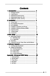
... Layout (G Pro 6 1.4 Motherboard Layout (GV Pro 7 1.5 ASRock I/OTM (G Pro / GV Pro 8
2 Installation 9
2.1 Screw Holes 9 2.2 Pre-installation Precautions 9 2.3 CPU Installation 9 2.4 Installation of Heatsink and CPU fan 10 2.5 Installation of Memory Modules (DIMM 10 2.6 Expansion Slots 11 2.7 Jumpers Setup 12 2.8 Connectors 12
3 BIOS Setup 15
3.1 BIOS Setup Program 15 3.1.1 BIOS Menu...
User Manual - Page 4
... Contents
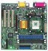
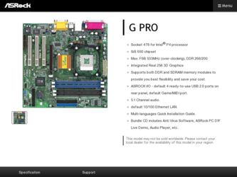
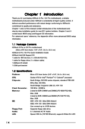
ASRock G Pro or GV Pro motherboard (Micro ATX form factor: 9.6" x 9.6", 24.4 x 24.4 cm)
ASRock G Pro / GV Pro Quick Installation Guide ASRock Intel-SiS Support CD 1 cable for IDE devices (1 x ATA 66/100/133) 1 cable for floppy drive (1 x ribbon cable) 1 ASRock I/O shield 1 COM port bracket
1.2 Specifications
Platform: CPU: Chipsets:
Clock Generator: Memory:
IDE:
Floppy Port: Audio: LAN...
User Manual - Page 5
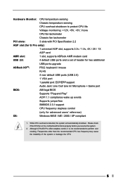
...and a set of header for two additional
USB ports upgrade
ASRock I/OTM:
PS/2: keyboard / mouse
RJ 45
4 rear default USB ports (USB 2.0)
1 VGA port
1 parallel port: ECP/EPP support
Audio Jack: Line Out/ Line In/ Microphone + Game port
BIOS:
AMI legal BIOS
Supports "Plug and Play"
ACPI 1.1 compliance wake up events
Supports jumperfree
SMBIOS 2.3.1 support
CPU frequency stepless control...
User Manual - Page 9
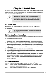
Chapter 2 Installation
G Pro / GV Pro is a Micro ATX form factor (9.6" x 9.6", 24.4 x 24.4 cm) motherboard. Before you install the motherboard, study the configuration of your chassis to ensure that the motherboard fits into it.
Make sure to unplug the power cord before installing or removing the motherboard. Failure to do so may cause physical injuries to you and damages to motherboard components...
User Manual - Page 10
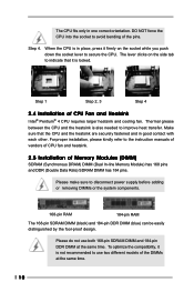
... the instruction manuals of vendors of CPU fan and heatsink.
2.5 Installation of Memory Modules (DIMM)
SDRAM (Synchronous DRAM) DIMM (Dual In-line Memory Module) has 168 pins and DDR (Double Data Rate) SDRAM DIMM has 184 pins.
Please make sure to disconnect power supply before adding or removing DIMMs or the system components.
168-pin RAM
184-pin RAM...
User Manual - Page 11
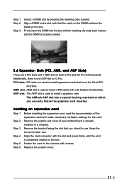
... slot on both G Pro and GV Pro motherboards. Additionally, there is one AGP slot on G Pro. PCI slots: PCI slots are used to install expansion cards that have the 32-bit PCI
interface. AMR slot: AMR slot is used to insert AMR cards with v.92 Modem functionality. AGP slot: The AGP slot is used to install a graphics card.
The ASRock AGP slot has a special...
User Manual - Page 15
...
This section explains how to configure your system using the BIOS Setup Utility. The Flash Memory on the motherboard stores the BIOS Setup Utility. When you start up the computer, there is a chance for you to run the BIOS Setup. Press during the Power-On-Self-Test (POST) to enter the BIOS Setup Utility, otherwise, POST continues with its test routines. If you...
User Manual - Page 16
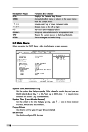
... Advanced
System Date System Time
Floppy Drives IDE Devices
BIOS Version Processor Type Processor Speed Cache Size Microcode Update Total Memory
DDR1 DDR2 SDR1 SDR2
AMIBIOS SETUP UTILITY - VERSION 3.31a Security Power Boot Exit
Oct 14 2002 Mon 17:07:40
[ Setup Help ]
Month: Jan - Dec Day: 01 - 31 Year: 1980 - 2099
GE-PRO BIOS L0.10 Generic-X86 2000 MHz 512 KB
F23 / 08...
User Manual - Page 17
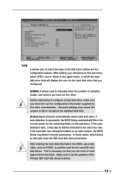
... already formatted on an older system, the BIOS Setup may detect incorrect parameters. In these cases, select [User] to manually enter the IDE hard disk drive parameters.
After entering the hard disk information into BIOS, use a disk utility, such as FDISK, to partition and format new IDE hard disk drives. This is necessary so that you can write or read...
User Manual - Page 18
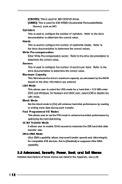
... to determine the correct value. Maximum Capacity This field shows the drive's maximum capacity as calculated by the BIOS based on the drive information you entered. LBA Mode This allows user to select the LBA mode for a hard disk > 512 MB under DOS and Windows; for Netware and UNIX user, select [Off] to disable the...
User Manual - Page 19
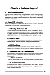
... the Support CD to display the menus.
4.2.2 Drivers Menu
The Drivers Menu shows the available devices drivers if the system detects installed devices. Install the necessary drivers to activate the devices.
4.2.3 Utilities Menu
The Utilities Menu shows the applications software that the motherboard supports. Click on a specific item then follow the installation wizard to install it.
4.2.4 ASRock PC...
User Manual - Page 21
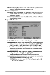
... value unless your PCI expansion cards' specifications require other settings. Primary Graphics Adapter: Select PCI, OnBoard VGA, or Add-on AGP as the primary graphics adapter.
Peripheral Configuration:
OnBoard FDC: Use this to enable or disable floppy drive controller. OnBoard Serial Port: Use this to set addresses for the onboard serial ports or
disable serial ports. Configuration options: [Auto...