ASRock P4S55FX driver and firmware
Related ASRock P4S55FX Manual Pages
Download the free PDF manual for ASRock P4S55FX and other ASRock manuals at ManualOwl.com
User Manual - Page 3
... (P4S55FX+/ P4S55FX 9
2 Installation 10
Pre-installation Precautions 10 2.1 CPU Installation 11 2.2 Installation of CPU Fan and Heatsink 11 2.3 Installation of Memory Modules (DIMM 12 2.4 Expansion Slots (PCI and AGP Slots 14 2.5 Jumpers Setup 15 2.6 Onboard Headers and Connectors 16 2.7 Serial ATA (SATA) Hard Disks Installation 19 2.8 Making An SATA Driver Diskette 20
3 BIOS Setup 21...
User Manual - Page 4
... Contents
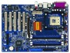
ASRock P4S55FX+ or P4S55FX Motherboard (ATX Form Factor: 12.0-in x 8.6-in, 30.5 cm x 21.8 cm)
ASRock P4S55FX+ / P4S55FX Quick Installation Guide ASRock P4S55FX+ / P4S55FX Support CD One 80-conductor Ultra ATA 66/100/133 IDE Ribbon Cable One Ribbon Cable for a 3.5-in Floppy Drive One Serial ATA (SATA) Cable (For P4S55FX+ Only) One Serial ATA (SATA) HDD Power Cable (For P4S55FX+ Only...
User Manual - Page 6
...ports,
1 RJ 45 port,
Audio Jack: Line In / Line Out / Microphone
BIOS:
AMI BIOS
Supports "Plug and Play"
ACPI 1.1 compliance wake up events
Supports jumperfree
SMBIOS 2.3.1 support
CPU frequency stepless control
(only for advanced users' reference, see CAUTION 5)
OS:
Microsoft® Windows® 98SE / ME / 2000 / XP compliant
CAUTION!
1. This motherboard supports Dual Channel Memory...
User Manual - Page 10
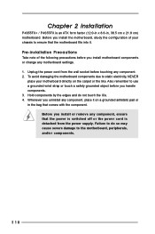
... 2 Installation
P4S55FX+ / P4S55FX is an ATX form factor (12.0-in x 8.6-in, 30.5 cm x 21.8 cm) motherboard. Before you install the motherboard, study the configuration of your chassis to ensure that the motherboard fits into it.
Pre-installation Precautions
Take note of the following precautions before you install motherboard components or change any motherboard settings. 1. Unplug the power cord...
User Manual - Page 11
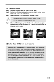
... lever clicks on the side tab to indicate that it is locked.
Step 1
Step 2, 3
Step 4
2.2 Installation of CPU Fan and Heatsink
This motherboard adopts 478-pin CPU socket to support Intel® Pentium® 4 / Celeron® CPU. It requires larger heatsink and cooling fan to dissipate heat. You also need to spray thermal grease between the...
User Manual - Page 12
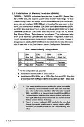
2.3 Installation of Memory Modules (DIMM)
P4S55FX+ / P4S55FX motherboard provides four 184-pin DDR (Double Data Rate) DIMM slots, and supports Dual Channel Memory Technology. For dual channel configuration, you always need to install identical (the same brand, speed, size and chip-type) DDR DIMM pair in the slots of the same color. In other words, you have to install identical...
User Manual - Page 13
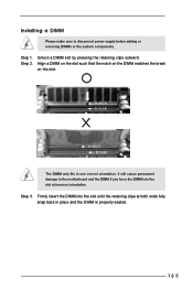
Installing a DIMM
Please make sure to disconnect power supply before adding or removing DIMMs or the system components.
Step 1. Step 2.
Unlock a DIMM slot by ...slot.
notch break
notch break
The DIMM only fits in one correct orientation. It will cause permanent damage to the motherboard and the DIMM if you force the DIMM into the slot at incorrect orientation.
Step 3. Firmly insert the DIMM into...
User Manual - Page 14
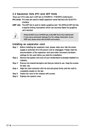
... and 1 AGP slot on P4S55FX+ / P4S55FX motherboard. PCI slots: PCI slots are used to install expansion cards that have the 32-bit PCI
interface. AGP slot: The AGP slot is used to install a graphics card. The ASRock AGP slot has
a special locking mechanism which can securely fasten the graphics card inserted.
Please do NOT use a 3.3V AGP card on the AGP slot of...
User Manual - Page 15
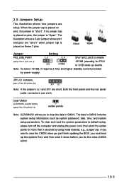
... system password, date, time, and system setup parameters. To clear and reset the system parameters to default setup, please turn off the computer and unplug the power cord, then short the solder points for more than 3 seconds by using metal material, e.g., a paper clip. If you need to clear the CMOS when you just finish updating the BIOS...
User Manual - Page 18
...
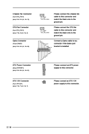
CPU_FAN_SPEED
Please connect the CPU fan cable to this connector and match the black wire to the ground pin.
+5V JBB1 JBX MIDI_OUT
JBY
JBB2
MIDI_IN
Connect a Game cable to this connector if the Game port bracket is installed.
1
+5V JAB2
JAY GND GND JAX JAB1 +5V
Please connect an ATX power supply to this connector...
User Manual - Page 19
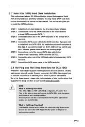
...Hard Disks Installation
This motherboard adopts SiS 964 southbridge chipset that supports Serial ATA (SATA) hard disks and RAID functions. You may install SATA hard disks on this motherboard for internal storage devices. This section will guide you to install the SATA hard disks.
STEP 1: Install the SATA hard disks into the drive bays of your chassis. STEP 2: Connect one end of the SATA data cable...
User Manual - Page 20
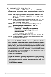
... the SATA driver diskette ready, you may start to install Windows 2000 / Windows XP on your system directly without setting the RAID configuration on your system, or you may start to use "SiS RAID BIOS Setting Utility" to set RAID 0 / RAID 1 / JBOD configuration before you install the OS. Before you start to configure the RAID function, you need to check the installation guide in the Support CD...
User Manual - Page 21
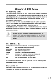
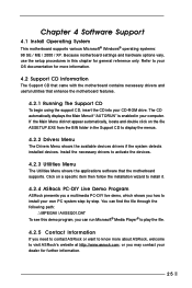
Chapter 3 BIOS Setup
3.1 BIOS Setup Utility
This section explains how to use the BIOS Setup Utility to configure your system. The Flash Memory on the motherboard stores the BIOS Setup Utility. You may run the BIOS Setup Utility when you start up the computer. Please press during the Power-On-Self-Test (POST) to enter the BIOS Setup Utility, otherwise, POST continues with its test routines. If you...
User Manual - Page 22
....
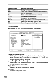
Main Advanced
System Date System Time
Floppy Drives IDE Devices
BIOS Version Processor Type Processor Speed Cache Size Microcode Update Total Memory
DDR1 DDR2 DDR3 DDR4
AMIBIOS SETUP UTILITY - VERSION 3.31a Security Power Boot Exit
Jan 2 2004 Fri 10:07:40
[ Setup Help ]
Month: Jan - Dec Day: 01 - 31 Year: 1980 - 2099
P4S55FX+ BIOS P1.00 Pentium (R) 4 CPU 2400 MHz 512 KB F27 / 33 256...
User Manual - Page 23
... already formatted on an older system, the BIOS Setup may detect incorrect parameters. In these cases, select [User] to manually enter the IDE hard disk drive parameters.
After entering the hard disk information into BIOS, use a disk utility, such as FDISK, to partition and format new IDE hard disk drives. This is necessary so that you can write or read...
User Manual - Page 24
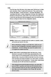
... to determine the correct value. Maximum Capacity This field shows the drive's maximum capacity as calculated by the BIOS based on the drive information you entered. LBA Mode This allows user to select the LBA mode for a hard disk > 512 MB under DOS and Windows; for Netware and UNIX user, select [Off] to disable the...
User Manual - Page 25
... the Support CD to display the menus.
4.2.2 Drivers Menu
The Drivers Menu shows the available devices drivers if the system detects installed devices. Install the necessary drivers to activate the devices.
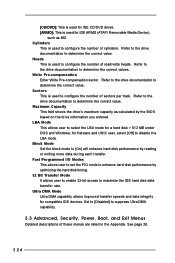
4.2.3 Utilities Menu
The Utilities Menu shows the applications software that the motherboard supports. Click on a specific item then follow the installation wizard to install it.
4.2.4 ASRock PC...
User Manual - Page 26
... a computer system with an Intel Pentium®4 processor that supports Hyper-Threading technology and an operating system that includes optimization for this technology, such as Microsoft® Windows® XP. Set to [Auto] if using Microsoft® Windows® XP, or Linux kernel version 2.4.18 or higher. This option will be hidden if the current CPU does not support...
User Manual - Page 27
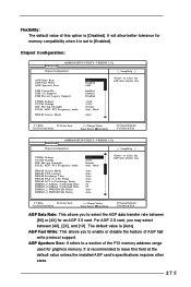
...]. It will allow better tolerance for memory compatibility when it is set to [Enabled].
Chipset Configuration:
Advanced
AMIBIOS SETUP UTILITY - VERSION 3.31a
Chipset Configuration
[ Setup Help ]
AGP Data Rate AGP Fast Write AGP Aperture Size
USB Controller USB 2.0 Support USB Device Legacy Support
VDDQ Voltage VCCM Volatge IDE Driving Strength ZCLK / AGP / PCI Frequency mode
DRAM Access Mode...
User Manual - Page 30
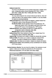
... select Midi IRQ. OnBoard Game Port: Select address for Game Port or disable Game Port.
Configuration options: [Disabled], [200], [208]. OnBoard IDE: This allows you to enable or disable the onboard IDE controller. OnBoard SATA: This allows you to enable or disable the onboard SATA
controller. This option is available only for P4S55FX+ motherboard. OnBoard LAN: This allows you to enable...