ASRock P4S61 driver and firmware
Related ASRock P4S61 Manual Pages
Download the free PDF manual for ASRock P4S61 and other ASRock manuals at ManualOwl.com
User Manual - Page 3
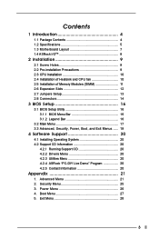
...12 2.7 Jumpers Setup 13 2.8 Connectors 14
3 BIOS Setup 16
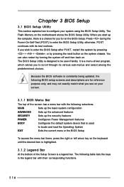
3.1 BIOS Setup Utility 16 3.1.1 BIOS Menu Bar 16 3.1.2 Legend Bar 16
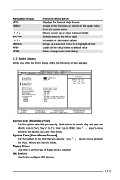
3.2 Main Menu 17 3.3 Advanced, Security, Power, Boot, and Exit Menus ...... 19
4 Software Support 20
4.1 Installing Operating System 20 4.2 Support CD Information 20
4.2.1 Running Support CD 20 4.2.2 Drivers Menu 20 4.2.3 Utilities Menu 20 4.2.4 ASRock "PC-DIY...
User Manual - Page 4
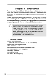
... memory and CPU support lists on ASRock website as well. ASRock website http://www.asrock.com
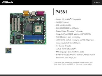
1.1 Package Contents
ASRock P4S61 Motherboard (Micro ATX Form Factor: 9.6-in x 8.4-in, 24.4 cm x 21.3 cm)
ASRock P4S61 Quick Installation Guide ASRock P4S61 Support CD One 80-conductor Ultra ATA 66/100/133 IDE Ribbon Cable One Ribbon Cable for a 3.5-in Floppy Drive One ASRock I/OTM Shield One COM Port...
User Manual - Page 6
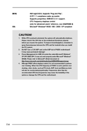
...® Windows® 98/ME. Please refer to Microsoft® official document at http://www.microsoft.com/whdc/hwdev/bus/USB/USB2support.mspx
4. Although P4S61 offers stepless control, it is not recommended to perform over clocking. When the CPU frequency of P4S61 is set to perform over clocking, other clocks, such as PCI clock, AGP clock and Memory clock will...
User Manual - Page 9
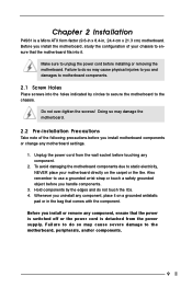
... 2 Installation
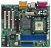
P4S61 is a Micro ATX form factor (9.6-in x 8.4-in, 24.4 cm x 21.3 cm) motherboard. Before you install the motherboard, study the configuration of your chassis to ensure that the motherboard fits into it.
Make sure to unplug the power cord before installing or removing the motherboard. Failure to do so may cause physical injuries to you and damages to motherboard...
User Manual - Page 10

... is also needed to improve heat dissipation. Make sure that the CPU and the heatsink are securely fastened and in good contact with each other. Then connect the CPU fan to the CPU_FAN connector (CPU_FAN1, see page 7, No. 5). For proper installation, please kindly refer to the instruction manuals of the CPU fan and heatsink vendors.
10
User Manual - Page 11
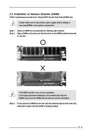
2.5 Installation of Memory Modules (DIMM)
P4S61 motherboard provides three 184-pin DDR (Double Data Rate) DIMM slots.
Please make sure to disconnect power supply before adding or removing DIMMs or the system components...
The DIMM only fits in one correct orientation. It will cause permanent damage to the motherboard and the DIMM if you force the DIMM into the slot at incorrect orientation. Step ...
User Manual - Page 12
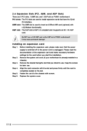
..., and 1 AGP slot on P4S61 motherboard. PCI slots: The PCI slots are used to install expansion cards that have the 32-bit
PCI interface. AMR slot: The AMR slot is used to insert an ASRock MR card (optional) with
v.92 Modem functionality. AGP slot: The AGP slot is AGP 3.5 compliant and it supports an 8X / 4X AGP
card. Do NOT use a 3.3V...
User Manual - Page 16
...
This section explains how to configure your system using the BIOS Setup Utility. The Flash Memory on the motherboard stores the BIOS Setup Utility. When you start up the computer, there is a chance for you to run the BIOS Setup. Press during the Power-On-Self-Test (POST) to enter the BIOS Setup Utility, otherwise, POST continues with its test routines. If you...
User Manual - Page 17
... appears.
Main Advanced
System Date System Time
Floppy Drives IDE Devices
BIOS Version Processor Type Processor Speed Cache Size Microcode Update Total Memory
DDR1 DDR2 DDR3
AMIBIOS SETUP UTILITY - VERSION 3.31a Security Power Boot Exit
Oct17 2003 Fri 20:07:40
[ Setup Help ]
Month: Jan - Dec Day: 01 - 31 Year: 1980 - 2099
P4S61 BIOS P1.00 Pentium (R) 4 CPU 2400 MHz 512 KB
F29 / 11 224...
User Manual - Page 18
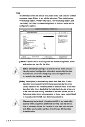
... already formatted on an older system, the BIOS Setup may detect incorrect parameters. In these cases, select [User] to manually enter the IDE hard disk drive parameters.
After entering the hard disk information into BIOS, use a disk utility, such as FDISK, to partition and format new IDE hard disk drives. This is necessary so that you can write or read...
User Manual - Page 19
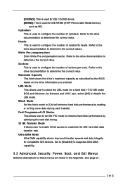
... to determine the correct value. Maximum Capacity This field shows the drive's maximum capacity as calculated by the BIOS based on the drive information you entered. LBA Mode This allows user to select the LBA mode for a hard disk > 512 MB under DOS and Windows; for Netware and UNIX user, select [Off] to disable the...
User Manual - Page 20
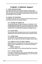
... Support CD to display the menus.
4.2.2 Drivers Menu
The Drivers Menu shows the available devices drivers if the system detects installed devices. Please install the necessary drivers to activate the devices.
4.2.3 Utilities Menu
The Utilities Menu shows the applications software that the motherboard supports. Click on a specific item then follow the installation wizard to install it.
4.2.4 ASRock...
User Manual - Page 21
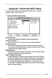
...: This shows current CPU host frequency of the installed motherboard.
CPU Ratio Selection: CPU Ratio is the multiple that times the front side bus frequency will equal the core speed of the installed processor. Whether the option is open or locked is determined by the installed processor.
DRAM Frequency: If [Auto] is selected, the motherboard will detect the memory module(s) inserted and...
User Manual - Page 26
... Power Boot Exit
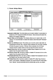
Suspend To RAM (S3) Repost Video on S3 Resume Restore on AC / Power Loss Ring-In Power On PCI Devices Power On PS / 2 Keyboard Power On RTC Alarm Power On
RTC Alarm Date RTC Alarm Hour RTC Alarm Minute RTC Alarm Second
Disabled Disabled Power Off Disabled Disabled Disabled Disabled Every Day 12 30 00
[ Setup Help ]
Set the power...