ASRock P4Twins-HDTV driver and firmware
Related ASRock P4Twins-HDTV Manual Pages
Download the free PDF manual for ASRock P4Twins-HDTV and other ASRock manuals at ManualOwl.com
User Manual - Page 3
...2.7.1 HDTV (High-Definition TV) Support Function ...... 20 2.7.2 TV Support Function 22 2.8 Untied Overclocking Technology 23 2.9 Serial ATA (SATA) Hard Disks Installation 23 2.10 Making a SATA Driver Diskette For SATA Operation in "RAID" Mode 23
3 BIOS SETUP UTILITY 25
3.1 Introduction 25 3.1.1 BIOS Menu Bar 25 3.1.2 Navigation Keys 26
3.2 Main Screen 26 3.3 Advanced Screen 27
3.3.1 CPU...
User Manual - Page 4
3.6 Security Screen 39 3.7 Exit Screen 40
4 Software Support 41
4.1 Install Operating System 41 4.2 Support CD Information 41
4.2.1 Running Support CD 41 4.2.2 Drivers Menu 41 4.2.3 Utilities Menu 41 4.2.4 Contact Information 41
4
User Manual - Page 5
...memory and CPU support lists on ASRock website as well. ASRock website http://www.asrock.com
1.1 Package Contents
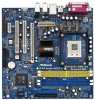
ASRock P4Twins-HDTV Motherboard (Micro ATX Form Factor: 9.6-in x 9.6-in, 24.4 cm x 24.4 cm)
ASRock P4Twins-HDTV Quick Installation Guide ASRock P4Twins-HDTV Support CD One 80-conductor Ultra ATA 66/100/133 IDE Ribbon Cable One Ribbon Cable for a 3.5-in Floppy Drive One Serial ATA (SATA...
User Manual - Page 7
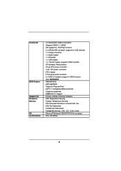
Connector
BIOS Feature Support CD Hardware Monitor OS Certifications
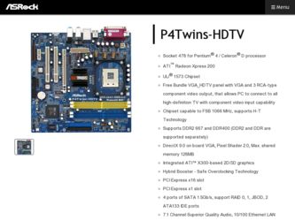
- 4 x Serial ATA 1.5Gb/s connectors (Supports RAID 0, 1, JBOD) (No support for "Hot Plug" function)
- 2 x ATA133 IDE connector (supports 4 x IDE devices) - 1 x Floppy connector - 1 x Game header - 1 x IR header - 1 x VGA header - 1 x TV-OUT header (supports YPbPr and AV) - CPU/Chassis FAN connector - 20 pin ATX power connector -...
User Manual - Page 8

... thermal grease between the CPU and the heatsink when you install the PC system. 5. For microphone input, this motherboard supports both stereo and mono modes. For audio output, this motherboard supports 2-channel, 4-channel, 6-channel, and 8-channel modes. Please check the table on page 10 for proper connection. 6. Power Management for USB 2.0 works fine under Microsoft® Windows® XP SP1...
User Manual - Page 11
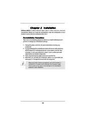
... 2 Installation
P4Twins-HDTV is a Micro ATX form factor (9.6-in x 9.6-in, 24.4 cm x 24.4 cm) motherboard. Before you install the motherboard, study the configuration of your chassis to ensure that the motherboard fits into it.
Pre-installation Precautions
Take note of the following precautions before you install motherboard components or change any motherboard settings. 1. Unplug the power cord...
User Manual - Page 12
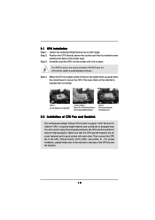
... Lever Up to 90°
STEP 2/STEP 3: Match The CPU Marked Corner to The Socket Marked Corner
STEP 4: Push Down And Lock The Socket Lever
2.2 Installation of CPU Fan and Heatsink
This motherboard adopts 478-pin CPU socket to support Intel® Pentium® 4 / Celeron® CPU. It requires larger heatsink and cooling fan to dissipate heat...
User Manual - Page 13
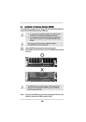
... DDRII slot or DDRII into DDR slot;otherwise, this motherboard and DIMM may be damaged.
2. It is not allowed to install both DDR and DDRII to this motherboard at the same time; otherwise, this motherboard and DIMM may be damaged.
Please make sure to disconnect power supply before adding or removing DIMMs or the system...
User Manual - Page 14
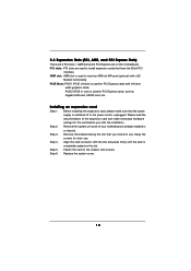
... motherboard. PCI slots: PCI slots are used to install expansion cards that have the 32-bit PCI
interface. AMR slot: AMR slot is used to insert an ASRock MR card (optional) with v.92
Modem functionality. PCIE Slots: PCIE1 (PCIE x16 slot) is used for PCI Express cards with x16 lane
width graphics cards. PCIE2 (PCIE x1 slot) is used for PCI Express cards, such as Gigabit LAN card, SATA2 card...
User Manual - Page 15
...
Setting
Description
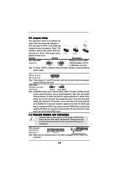
PS2_USB_PWR1
1_2
(see p.9 No. 1)
2_3
Short pin2, pin3 to enable
+5VSB (standby) for PS/2
+5V
+5VSB
or USB wake...setup,
please turn off the computer and unplug the power cord from the power
supply. After waiting for 15 seconds, use a jumper cap to short pin2 and pin3
on CLRCMOS1 for 5 seconds. However, please do not clear the CMOS right
after you update the BIOS...
User Manual - Page 18
... Connector
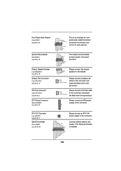
(3-pin CHA_FAN1) (see p.9 No. 17)
CPU Fan Connector
(3-pin CPU_FAN1) (see p.9 No. 5)
ATX Power Connector
(20-pin ATXPWR1) (see p.9 No. 34)
GND +5VA BACKOUT-R BACKOUT-L
1
A U D - O U T- L GND A U D - O U T- R MIC-POWER MIC
This is an interface for front panel audio cable that allows convenient connection and control of audio devices.
PLED+ PLEDPWRBTN# GND
1 DUMMY
RESET# GND HDLEDHDLED...
User Manual - Page 19
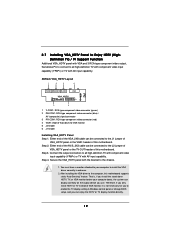
... the computer, this motherboard supports static "Auto Sensing" feature. That is, if you install the stand alone HDTV, TV, or VGA monitor before your computer boots, the system can display correctly on the output device you use. Therefore, if you only install HDTV or TV instead of VGA monitor, it is not necessary for you to enable the TV display setting in Windows control panel or change BIOS setup...
User Manual - Page 21
V Video tors
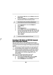
A. Click the Windows Start button, point at Settings, and then click
Control Panel.
B.
Double-click the Display icon, click the Settings tab, and use the
Screen Area slider to select the resolution you want.
If the resolution you select is not related to a specific timing, the system will reduce the resolution to the closest supported timing.
C.
Click the...
User Manual - Page 22
... OS.
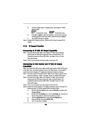
Step 4. Switch the monitor display to TV display and select proper TV format. For
selecting proper TV format, please follow the below steps:
A. Click the Windows Start button, point at Settings, and then click
Control Panel.
B.
Double-click the Display icon, click the Settings tab, and use the
Screen Area slider to select the resolution you want.
C.
Click the Advanced...
User Manual - Page 23
... chipset that supports Serial ATA (SATA) hard disks and RAID functions (RAID 0, 1, JBOD). You may install SATA hard disks on this motherboard for internal storage devices. This section will guide you to install the SATA hard disks.
STEP 1: Install the SATA hard disks into the drive bays of your chassis. STEP 2: Connect the SATA power cable to the SATA hard disk. STEP 3: Connect one end of the SATA...
User Manual - Page 24
... need to make a SATA driver before you start the OS installation.
STEP 1: Insert the ASRock Support CD into your optical drive to boot your system. (Do NOT insert any floppy diskette into the floppy drive at this moment!)
STEP 2: During POST at the beginning of system boot-up, press key, and then a window for boot devices selection appears. Please select...
User Manual - Page 25
...and then back on.
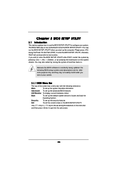
Because the BIOS software is constantly being updated, the following BIOS setup screens and descriptions are for reference...set up the advanced BIOS features
H/W Monitor To display current hardware status
Boot
To set up the default system device to locate and load the
Operating System
Security
To set up the security features
Exit
To exit the current screen or the BIOS SETUP...
User Manual - Page 28
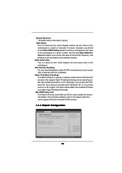
... installed processor.
Ratio Actual Value This is a read-only item, which displays the ratio actual value of this motherboard.
CPU Thermal Throttling You may select [Enabled] to enable P4 CPU internal thermal control mechanism to keep the CPU from overheated.
Hyper Threading Technology To enable this feature, it requires a computer system with an Intel Pentium®4 processor that supports Hyper...
User Manual - Page 33
... the example in the following instruction.
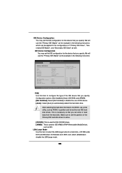
BIOS SETUP UTILITY Advanced
Primary IDE Master
Device Vendor Size LBA Mode Block Mode PIO Mode Async DMA Ultra DMA S.M.A.R.T.
Type LBA/Large Mode Block (Multi-Sector Transfer) PIO Mode DMA Mode S.M.A.R.T. 32Bit Data Transfer
:Hard Disk :ST340014A :40.0 GB :Supported :16Sectors :4 :MultiWord DMA-2 :Ultra DMA-5 :Supported
[Auto] [Auto] [Auto] [Auto...
User Manual - Page 41
...-ROM drive. The CD automatically displays the Main Menu if "AUTORUN" is enabled in your computer. If the Main Menu did not appear automatically, locate and double click on the file "ASSETUP.EXE" from the BIN folder in the Support CD to display the menus. 4.2.2 Drivers Menu The Drivers Menu shows the available devices drivers if the system detects installed devices. Please install...