Acer Aspire M5910 driver and firmware
Drivers and firmware downloads for this Acer Computers item

Related Acer Aspire M5910 Manual Pages
Download the free PDF manual for Acer Aspire M5910 and other Acer manuals at ManualOwl.com
Service Guide - Page 2
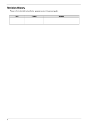
Revision History
Please refer to the table below for the updates made on this service guide.
Date
Chapter
Updates
ii
Service Guide - Page 4
... merchantability or fitness for any particular purpose. Any Acer Incorporated software described in this manual is sold or licensed "as is". Should the programs prove defective following their purchase, the buyer (and not Acer Incorporated, its distributor, or its dealer) assumes the entire cost of all necessary servicing, repair, and any incidental or consequential damages...
Service Guide - Page 5
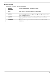
... this manual: SCREEN MESSAGES NOTE WARNING CAUTION IMPORTANT Denotes actual messages that appear on screen. Gives additional information related to the current topic. Alerts you to any physical risk or system damage that might result from doing or not doing specific actions. Gives precautionary measures to avoid possible hardware or software problems...
Service Guide - Page 9
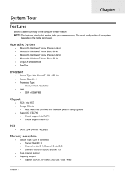
... Quantity: 1 Processor Type:
•
Intel Lynnfield / Clarkdale 95W + 65W FMB
•
FMB
•
Chipset
• •
PCH: Intel H57 Design Criteria:
•
Must meet Intel Lynnfield and Clarkdale platform design guides Should support Intel ASFC Should support Intel PECI
•
Super I/O: ITE8720
• •
PCB
•
uATX / 244*244mm / 4 Layers
Memory subsystem
•...
Service Guide - Page 10
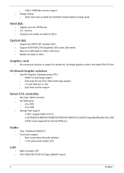
... cards in the single PSIe X16 slot
On-Board Graphic solution
•
Intel HD Graphics (Clarkdale series CPU)
DVMT 5.0 technology support Enhanced 3D and Clear Video technology support 1 D-sub VGA port on rear Dual View function support
Serial ATA controller
• •
Slot Type: SATA connector Six SATA ports:
• •
4 for HDD 2 for ODD 1.HDD : Support RAID 0/1/5/10 2.CD-ROM...
Service Guide - Page 16
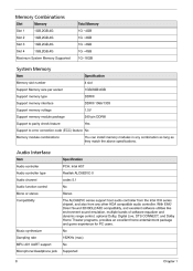
...4GB DDRIII DDRIII 1066/1333 1.5V 240-pin DDRIII Yes
Support to error correction code (ECC) feature No Memory module combinations You can install memory modules in any combination as long as they match the above specifications.
Audio Interface
Item Audio controller Audio controller type Audio channel Audio function control Mono or stereo Compatibility Specification PCH: Intel H57 Realtek ALC662VC...
Service Guide - Page 18
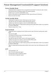
... support function)
Device Standby Mode
Independent power management timer for hard disk drive devices(0-15 minutes,time step=1minute). Hard Disk drive goes into Standby mode(for ATA standard interface). Disable V-sync to control the VESA DPMS monitor. Resume method:device activated (keyboard for DOS, keyboard &mouse for Windows. Resume recovery time 3-5sec
Global Standby Mode
Global power...
Service Guide - Page 22
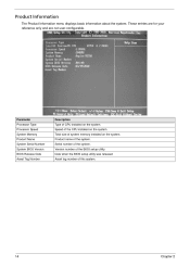
...menu displays basic information about the system. These entries are for your reference only and are not user-configurable.
Parameter Processor Type Processor Speed System Memory Product Name System Serial Number System BIOS Version BIOS Release Date Asset Tag Number
Description Type of CPU installed on the system. Speed of the CPU installed on the system. Total size of system memory installed on...
Service Guide - Page 38
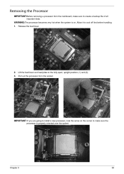
... the system is on. Allow it to cool off first before handling. 1. Release the load lever.
2. 3.
Lift the load lever and load plate to the fully open, upright position (1) and (2). Pull out the processor from the socket.
IMPORTANT: If you are going to install a new processor, note the arrow on the corner to make sure the...
Service Guide - Page 56
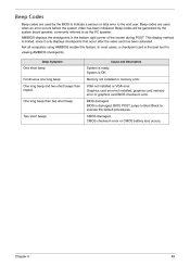
... computers using AMIBIOS enable this feature. In most cases, a checkpoint card is the best tool for viewing AMIBIOS checkpoints.
Beep Symptom Cause and Description
One short beep
System is ready. System is OK. Memory not installed or memory error. VGA not installed or VGA error. Graphics card error/not installed, graphics card memory error or graphics card BIOS checksum error. BIOS damaged. BIOS...
Service Guide - Page 57
... is enabled. Test base 512KB memory. Adjust policies and cache first 8MB. Set stack. Bootblock code is copied from ROM to lower system memory and control is given to it. BIOS now executes out of RAM. Copies compressed boot block code to memory in right segments. Copies BIOS from ROM to RAM for faster access. Performs main BIOS checksum and updates recovery status accordingly. Both key sequence...
Service Guide - Page 59
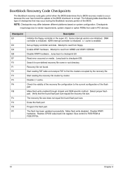
... the Bootblock recovery portion of the BIOS. NOTE: Checkpoints may differ between different platforms based on system configuration. Checkpoints maychange due to vendor requirements, system chipset or option ROMs from add-in PCI devices. Checkpoint E0 E9 EA EB EF F0 F1 F2 F3 F5 FA FB F4 FC FD FF Description Initialize the floppy controller in...
Service Guide - Page 64
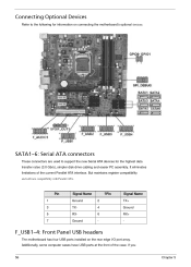
... to support the new Serial ATA devices for the highest data transfer rates (3.0 Gb/s), simpler disk drive cabling and easier PC assembly. It eliminates limitations of the current Parallel ATA interface. But maintains register compatibility
and software compatibility with Parallel ATA.
Pin 1 3 5 7
Signal Name Ground TXRXGround 2 4 6 -
?Pin
Signal Name TX+ Ground RX+ -
F_USB1~4: Front Panel USB...
Service Guide - Page 69
...the Aspire M5910(G) desktop computer. ...Service Guide. For Acer authorized service providers, your Acer office may have a ...Acer office to order FRU parts for service. To scrap or to return the defective parts, follow the local government ordinance or regulations on how to dispose it properly, or follow the rules set by your regional Acer office on how to return it. This document will be updated...
Service Guide - Page 70
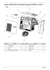
Aspire M5910(G) Exploded Diagram(AM551 ASSY)
NOTE: This section will be updated when more information becomes available.
ITEM 1 2 3 4 CHASSIS ASM TOP-COVER ODD
NAME
Q'TY 1 1 1 2
ITEM 5 6 7 8 FRONT BEZEL HDD COVER SIDE COVER POWER
NAME
Q'TY 1 1 1 1
REMOVABLE HDD CARRIER
62
Chapter 6
Service Guide - Page 71
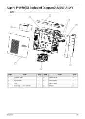
Aspire M5910(G) Exploded Diagram(AM550 ASSY)
NOTE: This section will be updated when more information becomes available.
ITEM 1 2 3 4 CHASSIS ASM TOP-COVER ODD
NAME
Q'TY 1 1 1 2
ITEM 5 6 7 8 FRONT BEZEL HDD COVER SIDE COVER POWER
NAME
Q'TY 1 1 1 1
REMOVABLE HDD CARRIER
Chapter 6
63