Acer Aspire X3910 driver and firmware
Drivers and firmware downloads for this Acer Computers item

Related Acer Aspire X3910 Manual Pages
Download the free PDF manual for Acer Aspire X3910 and other Acer manuals at ManualOwl.com
Service Guide - Page 1
Acer Aspire X3910 Service Guide
Service guide files and updates are available on the ACER/CSD web; for more information,
please refer to http://csd.acer.com.tw
PRINTED IN TAIWAN
Service Guide - Page 2

Revision History
Please refer to the table below for the updates made on this service guide.
Date
Chapter
Updates
ii
Service Guide - Page 4
... merchantability or fitness for any particular purpose. Any Acer Incorporated software described in this manual is sold or licensed "as is". Should the programs prove defective following their purchase, the buyer (and not Acer Incorporated, its distributor, or its dealer) assumes the entire cost of all necessary servicing, repair, and any incidental or consequential damages...
Service Guide - Page 5
... this manual:
SCREEN MESSAGES
Denotes actual messages that appear on screen.
NOTE
Gives additional information related to the current topic.
WARNING CAUTION IMPORTANT
Alerts you to any physical risk or system damage that might result from doing or not doing specific actions.
Gives precautionary measures to avoid possible hardware or software problems...
Service Guide - Page 10
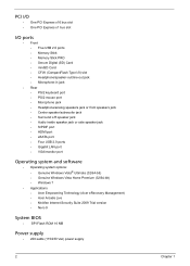
... • Center speaker/subwoofer jack • Surround L/R speaker jack • Audio inside speaker jack or side speaker jack • S/PDIF port • HDMI port • eSATA port • Four USB 2.0 ports • Gigabit LAN port • VGA/monitor port
Operating system and software
• Operating system options: • Genuine Windows Vista® Ultimate (32/64-bit) • Genuine...
Service Guide - Page 16
....
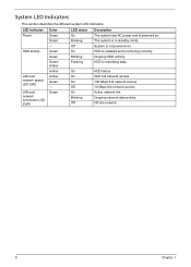
LED indicator Power
HDD activity
LAN port network speed LED (left) LAN port network connection LED (right)
Color Green Green - Green Green Green/ Amber Amber Amber Green - Green
LED status On Blinking Off On Blinking Flashing
Description The system has AC power and is powered on. The system is in standby mode. System is not powered on. HDD is installed and functioning...
Service Guide - Page 20
...
Asset Tag Number
:
@ 3.00GHz
Help Item
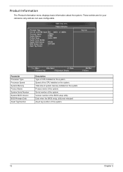
Parameter Processor Type Processor Speed System Memory Product Name System Serial Number System BIOS Version BIOS Release Date Asset Tag Number
:Move
Enter:Select
+/-/:Value
F1:General Help
F9:Optimized Defaults
ESC:Exit
F10:Save
Description Type of CPU installed on the system. Speed of the CPU installed on the system. Total size of system...
Service Guide - Page 28
...
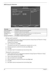
CMOS Setup Utility BIOS Security Features
Security Settings
Supervisor Password :Not Installed
User Password
:Not Installed
Change Supervisor Password Change User Password
[Press Enter] [Press Enter]
Help Item
Install or Change the password.
:Move
Enter:Select
+/-/:Value
F1:General Help
F9:Optimized Defaults
ESC:Exit
F10:Save
Parameter Supervisor Password User Password Change...
Service Guide - Page 33
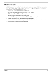
...that user should follow to flash BIOS ROM. 1. Prepare a Disk on Key (DOK) and keep it ready in hand.
(1). Connect the USB storage device to a USB port on your computer. (2). Save the AMIBoot.ROM to the USB storage device. (3). After saving the file, unplug the USB storage device. 2. Connect the USB storage device containing the DOK to a USB port on the system. 3. Press the power button to boot the...
Service Guide - Page 41
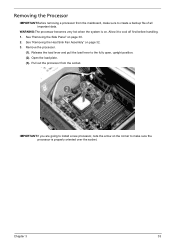
... "Removing the Heat Sink Fan Assembly" on page 32. 3. Remove the processor.
(1). Release the load lever and pull the load lever to the fully open, upright position. (2). Open the load plate. (3). Pull out the processor from the socket.
IMPORTANT:If you are going to install a new processor, note the arrow on the corner to make sure the...
Service Guide - Page 59
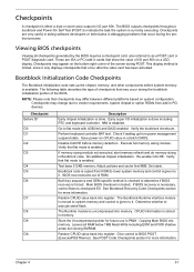
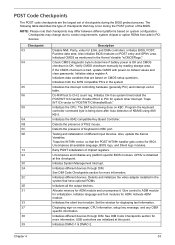
... additional chipset initialization. Re-enable CACHE. Verify that flat mode is enabled.
Test base 512KB memory. Adjust policies and cache first 8MB. Set stack.
Bootblock code is copied from ROM to lower system memory and control is given to it. BIOS now executes out of RAM.
Both key sequence and OEM specific method is checked to determine if BIOS recovery is...
Service Guide - Page 60
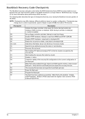
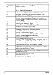
... chipset or option ROMs from add-in PCI devices.
Checkpoint E0
E9 EA EB EF E9 or EA F0 F1 F2
F3 F5 FA
FB
F4 FC FD FF
Description Initialize the floppy controller in the super I/O. Some interrupt vectors are initialized. DMA controller is initialized. 8259 interrupt controller is initialized. L1 cache is enabled. Set up floppy controller...
Service Guide - Page 61
... video adapter installed in the system that have optional ROMs.
Initializes all the output devices.
Allocate memory for ADM module and uncompress it. Give control to ADM module for initialization. Initialize language and font modules for ADM. Activate ADM module.
Initializes the silent boot module. Set the window for displaying text information.
Displaying sign-on message, CPU information, setup...
Service Guide - Page 62
... prepare for IPL detection. Initializes IPL devices controlled by BIOS and option ROMs. Generate and write contents of ESCD in NVRam. Log errors encountered during POST. Display errors to the user and gets the user response for error. Execute BIOS setup if needed / requested. Check boot password if installed. Late POST initialization of chipset registers. Program the peripheral parameters. Enable...
Service Guide - Page 63
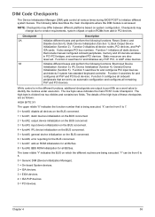
...0 disables all device nodes, PCI devices, and PnP ISA cards. It also assigns PCI bus numbers. Function 1 initializes all static devices that include manual configured onboard peripherals, memory and I/O decode windows in PCI-PCI bridges, and noncompliant PCI devices. Static resources are also reserved. Function 2 searches for and initializes any PnP, PCI, or AGP video devices.
Initialize different...
Service Guide - Page 64
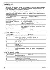
... Flash Program error 'AMIBOOT.ROM' file size error BIOS ROM image mismatch (file layout does not match image present in flash device)
POST BIOS Beep Codes
Number of Beeps 1 3 6 7 8
Description Memory refresh timer error. Base memory read/write test error Keyboard controller BAT command field General exception error (processor exception interrupt error) Display memory error (system video adapter...
Service Guide - Page 68
... imminent failure. This message can be reported by an ATAPI device using the S.M.A.R.T. error reporting standard. S.M.A.R.T. failure messages may indicate the need to replace the hard disk.
Virus Related
Message Displayed BootSector Write !!
VIRUS: Continue (Y/N)?
Description
The BIOS has detected software attempting to write to a drive's boot sector. This is flagged as possible virus activity...
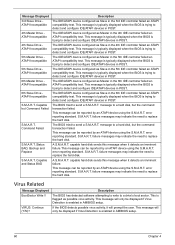
Service Guide - Page 69
... new CPU is installed in a motherboard with an outdated BIOS. In this case, the BIOS must be updated to include the Microcode Update for the new CPU.
There was an error in while validating the NVRAM data. This causes POST to clear the NVRAM data.
More than one system device is trying to use the same non-shareable resources (Memory or...
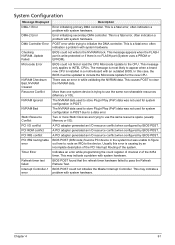
Service Guide - Page 71
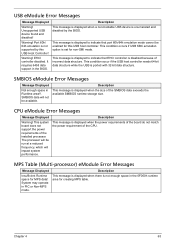
... by this USB Host Controller!
Warning! EHCI controller disabled. It requires 64bit data support in the BIOS.
Description This message is displayed when a non-bootable USB device is enumerated and disabled by the BIOS.
This message is displayed to indicate that port 60h/64h emulation mode cannot be enabled for this USB host controller. This condition occurs if USB KBC emulation option is set for...
Service Guide - Page 72
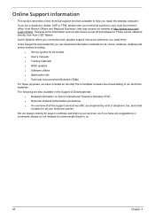
... can be obtained directly from Acer CSD Taiwan. Acer's Website offers you convenient and valuable support resources whenever you need them. In the Support & Downloads tab you can download information materials for all of Acer notebook, desktop and server models including:
q Service guides for all models q User's manuals q Training materials q BIOS updates q Software utilities q Spare parts lists...