Asus AP1400R driver and firmware


Related Asus AP1400R Manual Pages
Download the free PDF manual for Asus AP1400R and other Asus manuals at ManualOwl.com
AP1400R 1U Server Manual English Edition - Page 2
... are released for each product design represented by the digit before and after the period of the manual revision number. Manual updates are represented by the third digit in the manual revision number. For previous or updated manuals, BIOS, drivers, or product release information, contact ASUS at http://www.asus.com.tw or through any of the means indicated on the following...
AP1400R 1U Server Manual English Edition - Page 4
... for a Class B digital device, pursuant to Part 15 of the FCC Rules. These limits are designed to provide reasonable protection against harmful interference in a residential installation. This equipment generates, ...the dealer or an experienced radio/TV technician for help.
WARNING! The use of shielded cables for connection of the monitor to the graphics card is required to assure compliance with...
AP1400R 1U Server Manual English Edition - Page 5
...devices.
Operation Safety
IMPORTANT
• Any operation on this server must be conducted by certified or experienced engineers.
• Before operating your server, carefully read all the manuals included with the server package.
• Before using the server, make sure all cables are correctly connected and the power cables...is powered on, heat sinks and the surfaces of certain IC devices may ...
AP1400R 1U Server Manual English Edition - Page 6
... with different electrical potentials.
CAUTION
This product is equipped with a three-wire power cable and plug for the user's safety. Use the power cable with a properly grounded electrical outlet to avoid electrical shock.
IMPORTANT
Motherboards, adapters, and disk drives are sensitive to static electricity discharge. These devices are wrapped in antistatic bags to prevent this damage. Take the...
AP1400R 1U Server Manual English Edition - Page 7
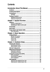
... 18 Monitor Connection 18 Power Connection 18 Power ON 18 Check LED 18
Chapter 3: Hardware Setup 19
Opening the Chassis 20 Unlocking the Cover 20 Removing the Cover 21
Internal Components 22 Motherboard Placement 23
Placement Direction 23 Motherboard Screws 23 Central Processing Unit (CPU 24 CPU Orientation 24 CPU Socket Locations 24 CPU Installation 25 CPU Heatsink 26 Attaching...
AP1400R 1U Server Manual English Edition - Page 8
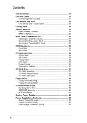
... PCI Card 32 SCSI Backplane 33 Front Side 33 Back Side 33 Connecting Cables 34 SCSI Cable 34 IDE Cable 34 Floppy Cable 35 LED Cable 35 Power Cables 36 Cooling Fan Cables 36 CD-ROM Drive 37 CD-ROM Mounting 37 CD-ROM Adapter Board 38 CD-ROM Installation 38 Floppy Drive 39 Floppy Drive Mounting 39 Floppy Drive Installation 39 SCSI Hard Disk Drives 40 Hot-Swap Drive Tray 40 SCSI...
AP1400R 1U Server Manual English Edition - Page 10
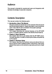
... with hardware knowledge of personal computers.
Contents Description
This manual contains the following parts: 1. Introduction: About This Manual
This part contains an introduction ... AP1400R server. The basic operation includes connecting the cables and powering on the system. 4. Chapter 3: Hardware Setup This chapter describes the hardware setup procedures that you have to perform when installing ...
AP1400R 1U Server Manual English Edition - Page 11
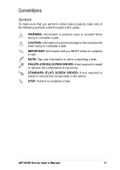
... certain tasks properly, take note of the following symbols used throughout this guide.
WARNING: Information to prevent injury to yourself when trying to complete a...DRIVER: A tool required to install or remove the components in the server. STANDARD (FLAT) SCREW DRIVER: A tool required to install or remove the components in the server. STEP: Actions to complete a task.
AP1400R Server User's Manual...
AP1400R 1U Server Manual English Edition - Page 16
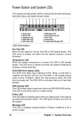
... LED 4. HDD0 Status LED 5. HDD1 Status LED
6. HDD2 Status LED 7. Hard Disk Activity LED 8. Power LED 9. Power Button 10. Programmable Message LED
LED Information
Fan Fail LED When the fan speed is...SCSI HDD Drive Status LEDs The SCSI hard disks have individual LEDs. When a hard disk is installed, the specific LED for that hard disk is ON (steady green) under normal conditions. When the disk...
AP1400R 1U Server Manual English Edition - Page 19
Chapter 3
This chapter describes the hardware setup procedures that you have to perform when installing system components. It also gives detailed information on the internal components and how to install them.
Hardware Setup
AP1400R Server User's Manual
19
AP1400R 1U Server Manual English Edition - Page 20
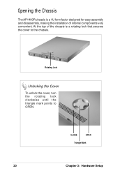
Opening the Chassis
The AP1400R chassis is a 1U form factor designed for easy assembly and disassembly, making the installation of internal components very convenient. At the top of the chassis is a rotating lock that secures the cover to the chassis.
Checklist
Rotating Lock
Unlocking ...
AP1400R 1U Server Manual English Edition - Page 23
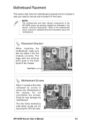
... other internal components of the AP1400R server are already installed as indicated in the section "Internal Components". Refer to the motherboard user's manual for detailed technical information about the motherboard.
Placement Direction
When installing the motherboard, make sure that you place it into the chassis correctly. The edge with the external ports goes to the back panel of...
AP1400R 1U Server Manual English Edition - Page 24
Safeguards
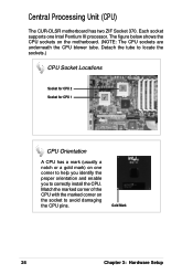
Central Processing Unit (CPU)
The CUR-DLSR motherboard has two ZIF Socket 370. Each socket supports one Intel Pentium III processor. The figure below shows the CPU sockets on the motherboard. (NOTE: The CPU sockets are underneath the CPU blower tube. Detach the tube to locate the sockets.)
CPU Socket Locations
Socket for CPU 2 Socket for CPU 1
CPU Orientation
A CPU has a mark (usually...
AP1400R 1U Server Manual English Edition - Page 25
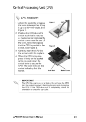
... indicating that it is locked.
Figure 1 Figure 2 Gold Mark
Marked Corner
IMPORTANT
The CPU fits only in one orientation. Do not force the CPU into the socket to prevent bending the pins and damaging the CPU. If the CPU does not fit completely, check its orientation or check for bent pins.
AP1400R Server User's Manual
25
AP1400R 1U Server Manual English Edition - Page 26
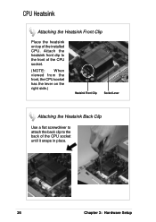
... the Heatsink Front Clip
Place the heatsink on top of the installed CPU. Attach the heatsink front clip to the front of the CPU socket.
(NOTE: When viewed from the front, the CPU socket has the lever on the right side.)
Heatsink Front Clip Socket Lever
Attaching the Heatsink Back Clip
Use a flat screwdriver...
AP1400R 1U Server Manual English Edition - Page 27
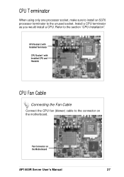
...S370 processor terminator to the unused socket. Install a CPU terminator as you would install a CPU. Refer to the section "CPU Installation".
CPU Socket 2 with Installed Terminator
CPU Socket 1 with Installed CPU and Heatsink
CPU Fan Cable
Connecting the Fan Cable
Connect the CPU fan (blower) cable to the connector on the motherboard.
Fan Connector on the Motherboard
AP1400R Server User's Manual...
AP1400R 1U Server Manual English Edition - Page 29
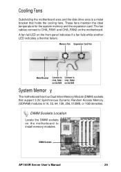
... CHA_FAN1 CHA_FAN2 on the M/B on the M/B
System Memor y
The motherboard has four Dual Inline Memory Module (DIMM) sockets that support 3.3V Synchronous Dynamic Random Access Memory (SDRAM) modules in 16, 32, 64, 128, 256, 512MB, or 1GB densities.
DIMM Sockets Location
Locate the DIMM sockets on the motherboard to install memory modules.
DIMM Sockets
AP1400R Server User's Manual
29
AP1400R 1U Server Manual English Edition - Page 30
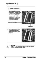
System Memor y
DIMM Installation
1. Unlock a DIMM socket by pressing the retaining clips outward. Align a DIMM on the socket such that the notches on the DIMM (indicated by white circles ... in place.
DIMM Notches
CAUTION
DIMMs fit in only direction. DO NOT force a DIMM into the socket to avoid damaging the DIMM.
30
Chapter 3: Hardware Setup
AP1400R 1U Server Manual English Edition - Page 31
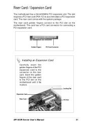
...PCI card connector for connecting a PCI expansion card.
Golden Fingers
PCI Card Connector
Installing an Expansion Card
Carefully insert the golden fingers of the PCI expansion card to the connector on the riser card. Insert the golden fingers of the riser card to the PCI slot on the motherboard until it fits in place.
Expansion Card
Riser Card
Locking Tab PCI Slot
AP1400R Server User's Manual...
AP1400R 1U Server Manual English Edition - Page 32
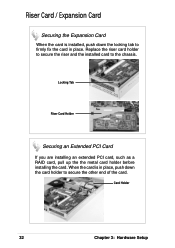
... secure the riser and the installed card to the chassis.
Locking Tab
Riser Card Holder
Securing an Extended PCI Card
If you are installing an extended PCI card, such as a RAID card, pull up the the metal card holder before installing the card. When the card is in place, push down the card holder to secure the other end of the card.
Card Holder
32
Chapter 3: Hardware Setup