Biostar P4M80-M7 driver and firmware

Related Biostar P4M80-M7 Manual Pages
Download the free PDF manual for Biostar P4M80-M7 and other Biostar manuals at ManualOwl.com
P4M80-M7 user's manual - Page 1
P4M80-M7
FCC Information and Copyright
This equipment has been tested and found to comply with the limits of a Class B digital device, pursuant to Part 15 of the FCC Rules. These limits are designed to provide reasonable protection against harmful interference in a residential installation...writing.
The content of this user's manual is subject to be changed without notice and we will not be...
P4M80-M7 user's manual - Page 2
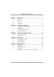
... 1
1.2
Package List 3
1.3
Layout 4
1.4
Components 5
Chapter 2:
2.1 2.2 2.3 2.4
Hardware Installation 6
Central Processing Unit (CPU 6 FAN Headers 7 Memory Module Installation 8 Connectors and Slots 9
Chapter 3:
3.1 3.2
Headers & Jumpers Setup 10
How to Setup Jumpers 10 Detail Settings 10
Chapter 4: Useful Help 14
4.1
Award BIOS Beep Code 14
4.2
Extra Information 14...
P4M80-M7 user's manual - Page 5
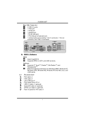
P4M80-M7
Rear Side Connectors 4 USB 2.0 ports. 1 VGA port. 1 serial port. 1 parallel port. 1 RJ-45 LAN jack. 1 PS/2 Mouse & Keyboard port. 1 vertical audio port including 1 line-in connector, 1 line out connector, and 1 MIC in connector.
PS/2 Mouse PS/2 Keyboard
Parallel
COM1 JCOM1
VGA1 JVGA1
LAN
USB x2
USB x2
Line In/ Surround Line Out Mic In 1/ Base/Center
B. BIOS & Software
BIOS Award ...
P4M80-M7 user's manual - Page 8
P4M80-M7
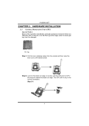
CHAPTER 2: HARDWARE INSTALLATION
2.1 CENTRAL PROCESSING UNIT (CPU) Special Notice:
Remove Pin Cap before installation, and make good preservation for future use. When the CPU is removed, cover the Pin Cap on the empty socket to ensure pin legs won't be damaged.
Pin Cap Step 1: Pull the lever sideways away ...
P4M80-M7 user's manual - Page 9
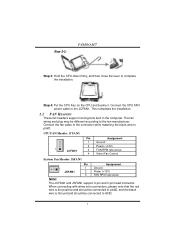
Step 2-2:
P4M80-M7
Step 3: Hold the CPU down firmly, and then close the lever to complete the installation.
Step 4: Put the CPU Fan on the CPU and buckle it. Connect the CPU FAN power cable to the JCFAN1. This completes the installation.
2.2 FAN HEADERS
These fan headers support cooling-fans built in the computer. The fan wiring and plug may be different according...
P4M80-M7 user's manual - Page 10
P4M80-M7
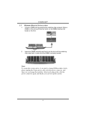
2.3
1.
MEMORY MODULE INSTALLATION
Unlock a DIMM slot by pressing the retaining clips outward. Align a DIMM on the slot such ... the system safety, if you need to change DDR modules, firstly, please unplug the 20-pin power cable with the power connector, and then you can change the modules. Afterwards, plug in the cable the power connector again, and finally you can boot up the system.
8
P4M80-M7 user's manual - Page 16
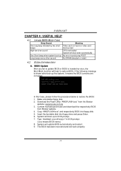
... motherboard model and download the respectively BIOS
from Biostar website. 4. Copy "AWDFLASH.exe" and respectively BIOS into floppy disk. 5. Insert the bootable disk into floppy drive and press Enter. 6. System will boot-up to DOS prompt. 7. Type "Awdflash xxxx.bf/sn/py/r" in DOS prompt.
(xxxx means BIOS name.) 8. System will update BIOS automatically and restart. 9. The BIOS has been recovered...
P4M80-M7 user's manual - Page 18
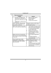
... snaps into place.
System does not boot from hard disk 1. drive, can be booted from optical drive.
Check cable running from disk to disk controller board. Make sure both ends are securely plugged in; check the drive type in the standard CMOS setup.
2. Backing up the hard drive is extremely important. All hard disks are capable of breaking down at any time.
System...
P4M80-M7 user's manual - Page 19
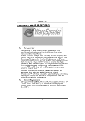
.... Also, in the About panel, you can get detail descriptions about BIOS model and chipsets. In addition, the frequency status of CPU, memory, AGP and PCI along with the CPU speed are synchronically shown on our main panel. Moreover, to protect users' computer systems if the setting is not appropriate when testing and results in system fail or...
P4M80-M7 user's manual - Page 20
P4M80-M7
5.3
1.
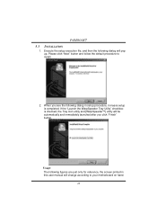
INSTALLATION
Execute the setup execution file, and then the following dialog will pop up. Please click "Next" button and follow the default procedure to install.
2. When you see the following dialog in setup procedure, it means setup is completed. If the "... are just only for reference, the screen printed in this user manual will change according to your motherboard on hand.
18
P4M80-M7 user's manual - Page 21
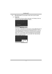
P4M80-M7 5.4 [WARPSPEEDER™] INCLUDES 1 TRAY ICON AND 5 PANELS
1. Tray Icon:
Whenever the Tray Icon utility is launched, it will display a little tray icon on the right side of Windows Taskbar.
This utility is responsible for conveniently invoking [WarpSpeeder™] Utility. You can use the mouse by clicking the left button in order to invoke...
P4M80-M7 user's manual - Page 22
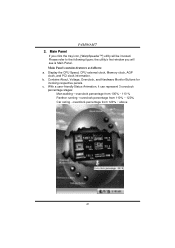
P4M80-M7 2. Main Panel
If you click the tray icon, [WarpSpeeder™] utility will be invoked. Please refer to the following figure; the utility's first window you will see is Main Panel. Main Panel contains features as follows: a. Display the CPU Speed, CPU external clock, Memory clock, AGP clock, and PCI clock information. b. Contains About, Voltage, Overclock, and Hardware...
P4M80-M7 BIOS guide - Page 2
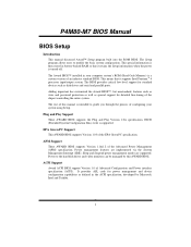
... it retains the Setup information when the power is turned off.
The Award BIOS™ installed in your computer system's ROM (Read Only Memory) is a custom version of an industry standard BIOS. This means that it supports Intel Pentium ® 4 processor input/output system. The BIOS provides critical low-level support for standard devices such as disk drives and serial and parallel ports.
Adding...
P4M80-M7 BIOS guide - Page 4
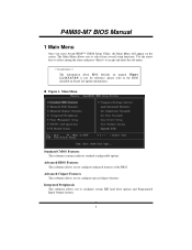
... Menu allows you to select from several setup functions. Use the arrow keys to select among the items and press to accept and enter the sub-menu.
!! WARNING !! The information about BIOS defaults on manual (Figure 1,2,3,4,5,6,7,8,9) is just for reference, please refer to the BIOS installed on board, for update information.
! Figure 1. Main Menu
Standard CMOS Features...
P4M80-M7 BIOS guide - Page 6
P4M80-M7 BIOS Manual
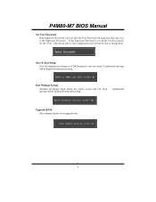
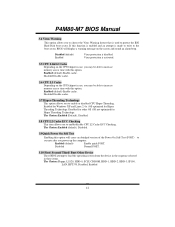
Set User Password If the Supervisor Password is not set, then the User Password will function in the same way as the Supervisor Password. If the Supervisor Password is set and the User Password is set, the "User" will only be able to view configurations but will not be able to change them.
Save & Exit Setup
Save all configuration changes to CMOS...
P4M80-M7 BIOS guide - Page 8
P4M80-M7 BIOS Manual
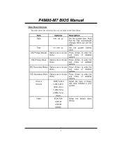
Main Menu Selections This table shows the selections that you can make on the Main Menu.
Item
Options
Description
Date
mm : dd : yy
Set the system date. Note that the 'Day' automatically changes when you set the date.
Time
hh : mm : ss
Set the system internal clock.
IDE Primary Master
Options are in its...
P4M80-M7 BIOS guide - Page 13
... an abridged version of the Power On Self-Test (POST) to
execute after you power up the computer.
Enabled (default)
Enable quick POST.
Disabled
Normal POST.
3.10 First/ Second/ Third/ Boot Other Device These BIOS attempt to load the operating system from the device in the sequence selected in these items. The Choices:Floppy, LS120, HDD-0, SCSI, CDROM, HDD...
P4M80-M7 BIOS guide - Page 15
P4M80-M7 BIOS Manual
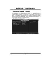
4 Advanced Chipset Features
This submenu allows you to configure the specific features of the chipset installed on your system. This chipset manage bus speeds and access to system memory resources, such as DRAM. It also coordinates communications with the PCI bus. The default settings that came with your system have been optimized and therefore should not be changed unless you...
P4M80-M7 BIOS guide - Page 24
P4M80-M7 BIOS Manual
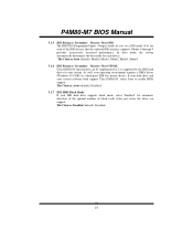
5.1.5
IDE Primary / Secondary Master / Slave PIO The IDE PIO (Programmed Input / Output) fields let you set a PIO mode (0-4) for each of the IDE devices that the onboard IDE interface supports. Modes 0 through 4 provides successively increased performance. In Auto mode, the system automatically determines the best mode for each device. The Choices:Auto (default), Mode0, ...
P4M80-M7 BIOS guide - Page 34
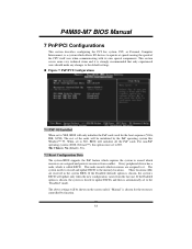
P4M80-M7 BIOS Manual
7 PnP/PCI Configurations
This section describes configuring the PCI bus system. PCI, or Personal Computer Interconnect, is a system which allows I/O devices to operate at speeds nearing the speed of the CPU itself uses when communicating with its own special components. This section covers some very technical items and it is strongly recommended that only experienced users ...