Canon PowerShot 350 driver and firmware
Related Canon PowerShot 350 Manual Pages
Download the free PDF manual for Canon PowerShot 350 and other Canon manuals at ManualOwl.com
Service Manual - Page 6
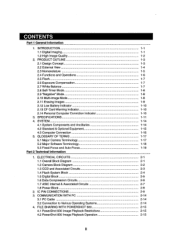
... 1.1 Overall Block Diagram 1.2 Camera Block Diagram 1.3 CCD and Associated Circuits 1.4 Flash System Block 1.5 Digital Block 1.6 Data Compression Circuits 1.7 ASIC Internal & Associated Circuits 1.8 Power Block
2. IC PIN CONNECTIONS 3. COMMUNICATION WITH PC
3.1 PC Cable 3.2 Connection to Various Operating Systems 4. FILE SHARING WITH POWERSHOT 600 4.1 PowerShot 600 Image Playback Restrictions...
Service Manual - Page 13
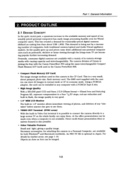
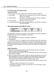
... TV are becoming popular further increasing demand. Presently, consumer digital cameras are available with a variety of in-camera storage media with varying capacity and interchangeability. The camera division of Canon is joining the fray with the Canon PowerShot 350 using the same interchangeable Compact Flash Memory (CF Card) used in the Canon PowerShot 600.
• Compact Flash Memory (CF Card...
Service Manual - Page 16
... by the unused space on the flash memory and the mode selected for the next shot. Depending on the actual content more images than indicated may be possible.
1) Install a CF card with open memory, set the Record mode and turn on the power switch. The Busy/Power lamp will light red. (When the power is first turned on, the LCD...
Service Manual - Page 19
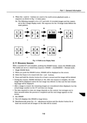
...card with 10 recorded images and the camera set in the 4 image display mode. The sequence for the 16 image mode follows the same pattern.
1 2
5 6
3 4
7 8
10
1 2
3 4
1 2
4
7 8
3 4
5 6
9 10
Fig. 1-4 Multi-screen Display Mode
2.11 ERASING IMAGES
With a recorded CF card installed..., ERASE will flash at 1Hz. After the erasure is complete, the next
image will be displayed unless the last...
Service Manual - Page 20
... the power
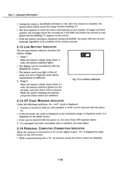
on. • In Record mode, the mark is displayed on the viewfinder image. In Playback mode, it is
displayed on the blank screen. • If the card is removed with the power on, the Auto Power Off sequence starts. 2. If a damaged card with unreadable data is installed, the mark lights.
2.14 PERSONAL COMPUTER CONNECTION INDICATOR
When the camera is...
Service Manual - Page 24
Part 1: General Information
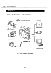
4. SYSTEM
4.1 SYSTEM COMPONENTS AND ANCILLARIES
Service Manual - Page 25
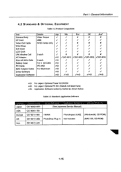
... Composition
Unit
Details
Jap
NA
Eur
UK
Aus*
Camera Body
Video Output
/
,/
X
X
X
CF Card
2MB
/
/
/
/
/
Video Out Cable
NTSC Areas only ,/
.,/
X
X
X
Wrist...Cable
IFC-35D
42 i
i
i
/
MAC Adapter Cable For Macintosh
0D©
./
,/
i
i
Driver Software
ita®
t/
./
V
/
Application Software
162 /op()
/430,
/4)O
4 ,6O
owl: For Japan: Optional Power...
Service Manual - Page 28
Part 1: General Information
5.2 MAJOR SOFTWARE TERMINOLOGY
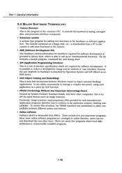
• Camera firmware This is the program in the camera's CPU. It controls the hardware's timing, manages files, and processes interface commands.
• Extension module A module-type program for adding new functions to the hardware or software application. The module contained on a floppy disk, etc., is downloaded from a PC to the ...
Service Manual - Page 34
..., AD APA, OB, KNEE RBIAS, V-SUB, LC
O REC(L)
O IRIS-A
IRIS-B
EVR
0 (SERIAL)
>co >0 a2C., «02
> 0 0 2
>co 2 0 a
>c9 a 2 0
o z 0
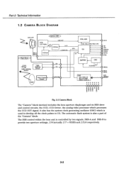
Fig. 2-2 Camera Block
The "Camera" block (section) includes the lens aperture diaphragm and its IRIS drive and control circuits. the CCD, CCD Driver, the analog video processor which processes the CCD OUT signal. It also has the system clock...
Service Manual - Page 46
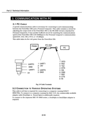
... volt power from the PowerShot 350.
PS350
IFC-35D
PC
UARTO GND UART1 5V
1 UART1 2 +5V 3 4 UARTO 5 GND
1 DCD 2 Rxd 3 Txd 4 DTR 5 SG 6 DSR 7 RST 8 CTS 9 RI
Fig. 2-9 Cable Terminals
3.2 CONNECTION TO VARIOUS OPERATING SYSTEMS
This cable is all that is required for connecting to a computer running DOS/V (WIN/TEL). To connect to a computer running the MAC O/S, the...
Service Manual - Page 53
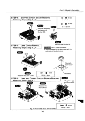
STEP 3: SHUTTER CIRCUIT BOARD REMOVAL
Necessary Steps: Step 1, 2, 3
Step 1 0X2
Step 2
Remove mounting hardware and Shutter CB.
Part 3: Repair Information
(BLAOI:
Service Manual - Page 56
Part 3: Repair Information
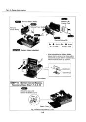
Step 3 Remove Battery Holder.
Step 4
Remove Cover Screw
Remove Tripod Socke
Step
Remove Left Chassis Plate
it
step 7 QX 2
a
CAUTION Battery Holder Installation
Step 8
Step 5
Remove Battery CB
e )
(BLACK)
M 1.4 x3mm
e (BLACK)
M 1.6 x 4mm
• When reinstalling the Battery Holder, insure that the arms on the three switches correctly couple ...
Service Manual - Page 63
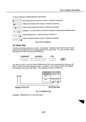
... occurs often on current tools because of software bug.s Rewrite the data.) •
Data transmission error. (Check if the power is turned on.) •
Failure communication with a camera. (Check the connection) •
Fig. 3-13 Error Indicator
3.2 BASIC USE
To write or read the data in a camera, "Command", "Address" and "Data" (this is unnecessary when reading) should be...
Service Manual - Page 119
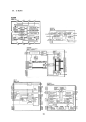
... 4 A5 A6 A7 A8 8
VDD VDD 6 VDD Vss Vss Vss 44
ROW ADDRESS BUFFER
COLUMN ADDRESS BUFFER
ROW DECODER
WORD DRIVER
BO
MEMOR CELL
SENSE AMP
COLUMN DECODER
.44
110 SELECTION
DATA
OUTPUT BUFFER
DATA OUTPUT
BUFFER
CONTROL L
-11.
OUTPUT
LEVEL SHIFT
POWER ON CLEAR
3 OUT 8 VDD
REGULATOR
Vss
NWE
2 DO 3 DI 4 02 5 D3 7 D4...