Dell Latitude C800 driver and firmware
Related Dell Latitude C800 Manual Pages
Download the free PDF manual for Dell Latitude C800 and other Dell manuals at ManualOwl.com
Service Manual - Page 10
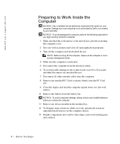
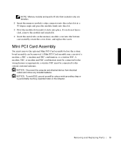
... in a power-management mode. 4 Make sure the computer is undocked. 5 Disconnect the computer from the electrical outlet. 6 To avoid possible damage to the system board, wait 10 to 20 seconds and then disconnect any attached devices. 7 Disconnect all other external cables from the computer. 8 Remove any installed PC Cards or plastic blanks from the PC Card slot. 9 Close the display and...
Service Manual - Page 11
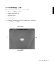
... Tools
The procedures in this manual require the following tools: • #1 magnetized Phillips screwdriver • Small flat-blade screwdriver • Small plastic scribe • Microprocessor extractor • Nonmarring tool • Flash BIOS upgrade program diskette or CD (provided when needed
to upgrade the system BIOS)
System Orientation
back of computer
left
right
front of...
Service Manual - Page 17
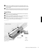
... due to servicing that is not authorized by Dell is not covered by your warranty. NOTICE: Unless otherwise noted, each procedure in this manual assumes that a part can be replaced by performing the removal procedure in reverse order.
Hard Drive
NOTICE: Disconnect the computer and attached devices from the electrical outlet and remove any installed batteries. NOTICE...
Service Manual - Page 18
... hard drive out.
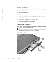
Replacing the Hard Drive 1 Gently push the hard drive into the drive bay until the drive door is flush with the computer case. 2 Push down on the drive until it snaps into place. 3 Replace the screw in the hard drive door.
Fixed Optical Drive
NOTICE: Disconnect the computer and attached devices from the electrical outlet and remove any installed batteries...
Service Manual - Page 19
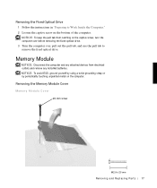
... from catching on the captive screw, turn the computer over before removing the fixed optical drive. 3 Turn the computer over, pull out the pull tab, and use the pull tab to remove the fixed optical drive.
Memory Module
NOTICE: Disconnect the computer and any attached devices from electrical outlets and remove any installed batteries. NOTICE: To avoid ESD, ground yourself...
Service Manual - Page 20
... p po rt. d ell. com
1 Follow the instructions in "Preparing to Work Inside the Computer." 2 Remove the screw. 3 Disengage the metal tabs at the opposite end of the cover.
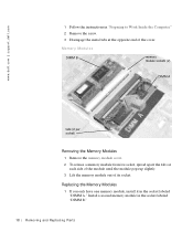
Memory Modules
DIMM B
memory module sockets (2)
DIMM A
tabs (2 per socket)
Removing the Memory Modules 1 Remove the memory module cover. 2 To release a memory module from its socket, spread apart the...
Service Manual - Page 21
... Mini PCI Card assembly before the system board assembly can be removed. A Mini PCI Card assembly may consist of a modem, a NIC, a modem and NIC combination, or a wireless NIC. A modem, NIC, or modem and NIC combination must be connected to the wiring harness as appropriate; a wireless NIC must be connected to the system's internal antenna.
NOTICE: Disconnect the computer and attached devices from...
Service Manual - Page 23
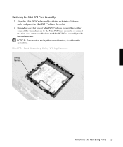
Replacing the Mini PCI Card Assembly 1 Align the Mini PCI Card assembly with the socket at a 45-degree angle, and press the Mini PCI Card into the socket. 2 Depending on what type of Mini PCI Card you are installing, either connect the wiring harness to the Mini PCI Card assembly, or connect the mini-coax antenna cable from the Mini PCI Card assembly to the...
Service Manual - Page 24
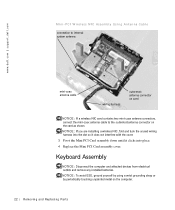
.... NOTICE: If you are installing a wireless NIC, fold and tuck the unused wiring harness into the slot so it does not interfere with the cover. 3 Pivot the Mini PCI Card assembly down until it clicks into place. 4 Replace the Mini PCI Card assembly cover.
Keyboard Assembly
NOTICE: Disconnect the computer and attached devices from electrical outlets and remove...
Service Manual - Page 27
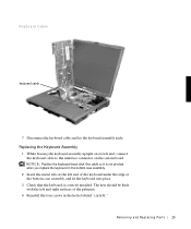
... the keyboard cable to the interface connector on the system board. NOTICE: Position the keyboard/track stick flex cable so it is... not pinched when you replace the keyboard in the bottom case assembly.
2 Insert the metal tabs at the left end of the keyboard under the edge of the bottom case assembly, and fit the keyboard into place.
3 Check that the keyboard is correctly installed...
Service Manual - Page 28
...w w.d el l.co m | su p po rt. d ell. com
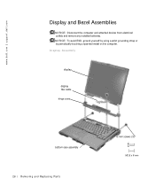
Display and Bezel Assemblies
NOTICE: Disconnect the computer and attached devices from electrical outlets and remove any installed batteries. NOTICE: To avoid ESD, ground yourself by using a wrist grounding strap or by periodically touching unpainted metal on the computer. Display Assembly
display
display flex cable hinge cover
bottom case assembly 26 Rem...
Service Manual - Page 36
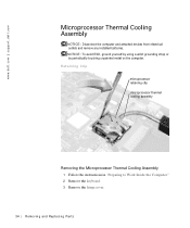
... and attached devices from electrical outlets and remove any installed batteries. NOTICE: To avoid ESD, ground yourself by using a wrist grounding strap or by periodically touching unpainted metal on the computer. Retaining Clip
microprocessor retaining clip microprocessor thermal cooling assembly
Removing the Microprocessor Thermal Cooling Assembly 1 Follow the instructions in "Preparing to...
Service Manual - Page 37
... by pivoting the top of the screwdriver toward the right side of the computer.
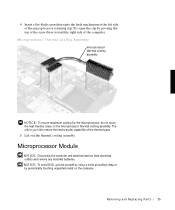
Microprocessor Thermal Cooling Assembly microprocessor thermal cooling assembly
NOTICE: To ensure maximum...out the thermal cooling assembly.
Microprocessor Module
NOTICE: Disconnect the computer and attached devices from electrical outlets and remove any installed batteries. NOTICE: To avoid ESD, ground yourself by using ...
Service Manual - Page 39
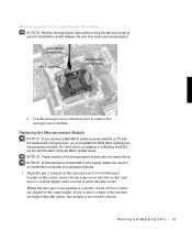
... module.
Replacing the Microprocessor Module
NOTICE: If you received a flash BIOS update program diskette or CD with the replacement microprocessor, you must update the BIOS after replacing the microprocessor module. For instructions on updating or reflashing the BIOS, see the Dell Portable Computer BIOS Update Guide. NOTICE: Proper seating of the microprocessor module does not require...
Service Manual - Page 40
..., insert a flat-blade screwdriver into the latch mechanism and pivot the top of the screwdriver away from the clip to close the latch.
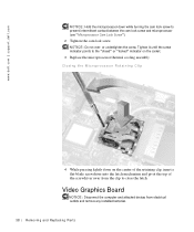
Video Graphics Board
NOTICE: Disconnect the computer and attached devices from electrical outlets and remove any installed batteries.
38 Rem o vi n g an d Rep l a ci n g Pa rt s
Service Manual - Page 42
... p po rt. d ell. com
NOTICE: Make sure the board is correctly and firmly seated before continuing. Failure to do so will cause intermittent video failures. 2 Replace the three screws.
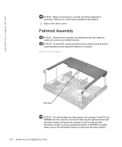
Palmrest Assembly
NOTICE: Disconnect the computer and attached devices from electrical outlets and remove any installed batteries. NOTICE: To avoid ESD, ground yourself by using...
Service Manual - Page 44

.... 9 Use the pull loop to disconnect the palmrest flex cable from the touch-
pad connector on the system board. 10 Carefully lift out the palmrest assembly.
Reserve Battery
NOTICE: Disconnect the computer and attached devices from electrical outlets and remove any installed batteries. NOTICE: To avoid ESD, ground yourself by using a wrist grounding strap or...
Service Manual - Page 46
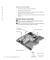
... bracket loosely in the palmrest, and connect the palmrest flex cable to the ZIF connector. 4 Replace the two 4-mm screws that secure the palmrest bracket to the palmrest.
System Board Assembly
NOTICE: Disconnect the computer and attached devices from electrical outlets and remove any installed batteries.
NOTICE: To avoid ESD, ground yourself by using a wrist...
Service Manual - Page 48
... the microprocessor module. For instructions on updating or reflashing the BIOS, see the Dell Portable Computer BIOS Update Guide.
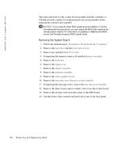
Removing the System Board 1 Follow the instructions in "Preparing to Work Inside the Computer." 2 Remove the hard drive and the fixed optical drive. 3 Remove any installed Mini PCI Cards. 4 If migrating the memory, remove all installed memory modules. 5 Remove the...
System Information Guide - Page 4
...that includes descriptions of
computer features, instructions on installing and configuring drivers and utilities, information on the system setup program, and instructions for attaching devices to the connectors on your computer's back panel. The User's Guide is located on your hard drive. You may also have one or more of the following documents:
• Documentation updates, which are sometimes...