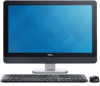
Dell OptiPlex 9020 AIO driver and firmware

Related Dell OptiPlex 9020 AIO Manual Pages
Download the free PDF manual for Dell OptiPlex 9020 AIO and other Dell manuals at ManualOwl.com
Owner's Manual - Page 2
...™ are trademarks of Advanced Micro Devices, Inc. Microsoft®, Windows®, MS-DOS®, Windows Vista®, the Windows Vista start button, and Office Outlook®...players. The Bluetooth® word mark is a registered trademark and owned by the Bluetooth® SIG, Inc. and any use of such mark by Dell Inc. is under license. Wi-Fi® is a registered trademark of Wireless Ethernet...
Owner's Manual - Page 3
... Optical Drive...19 Removing the Hard Drive...19 Installing the Hard Drive...20 Removing the Intrusion Switch...21 Installing the Intrusion Switch...22 Removing the Wireless Local Area Network (WLAN) Card 22 Installing the WLAN Card...23 Removing the Heat-Sink Assembly...23 Installing the Heat-Sink Assembly...23 Removing the Processor Fan...24 Installing the Processor Fan...24 Removing the Power...
Owner's Manual - Page 4
... (Graphics Card)...35 Removing the Antenna Module...36 Installing the Antenna Module...37 Removing the Display Panel...37 Installing the Display Panel...39 Removing the Camera...40 Installing the Camera...41
3 System Setup...43
Boot Sequence...43 Navigation Keys...43 System Setup Options...44 Updating the BIOS ...53 System and Setup Password...53
Assigning a System Password and Setup Password 54...
Owner's Manual - Page 5
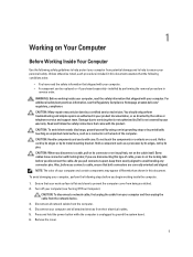
... Off Your Computer).
CAUTION: To disconnect a network cable, first unplug the cable from your computer and then unplug the cable from the network device. 3. Disconnect all network cables from the computer. 4. Disconnect your computer and all attached devices from their electrical outlets. 5. Press and hold the power button while the computer is unplugged to ground the system board. 6. Remove the...
Owner's Manual - Page 6
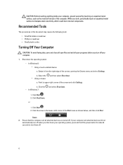
...off your computer.
1. Shut down the operating system:
- In Windows 8:
* Using a touch-enabled device:
a. Swipe in from the right edge of the screen, opening the Charms menu and select Settings.
b. ... computer and all attached devices are turned off. If your computer and attached devices did not
automatically turn off when you shut down your operating system, press and hold the power button...
Owner's Manual - Page 9
2
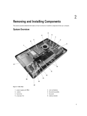
Removing and Installing Components
This section provides detailed information on how to remove or install the components from your computer.
System Overview
Figure 1. Inside View
1. power supply unit (PSU) 2. camera 3. hard drive 4. processor fan
5. coin-cell battery 6. heat sink assembly 7. heat sink 8. memory module
9
Owner's Manual - Page 11
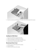
... the VESA stand to the computer and lift the VESA stand away from the computer.
Installing the VESA Stand
1. Align and place the VESA stand on the back of the computer. 2. Tighten the screws that secure the VESA stand to the computer. 3. Place and press the VESA cover on the computer, until it clicks into place...
Owner's Manual - Page 12
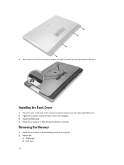
... cover on the back of the computer using the notches near the input/output (I/O) panel. 2. Tighten the screws to secure the back cover to the computer. 3. Install the VESA stand. 4. Follow the procedures in After Working Inside Your Computer.
Removing the Memory
1. Follow the procedures in Before Working Inside Your Computer. 2. Remove the:
a) VESA stand b) back...
Owner's Manual - Page 13
....
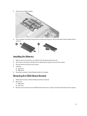
Installing the Memory
1. Align the notch on the memory-card with the tab in the system-board connector. 2. Press down on the memory module until the release tabs spring back to secure them in place. 3. Place the memory shield back into its place. 4. Install the:
a) back cover b) VESA stand 5. Follow the procedures in After Working Inside Your Computer.
Removing...
Owner's Manual - Page 14
... to the computer. 3. Install the:
a) back cover b) VESA stand 4. Follow the procedures in After Working Inside Your Computer.
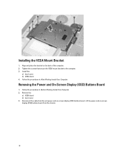
Removing the Power and On-Screen Display (OSD) Buttons Board
1. Follow the procedures in Before Working Inside Your Computer. 2. Remove the:
a) VESA stand b) back cover 3. Disconnect the cable from the and power and on-screen display (OSD) buttons board. Lift the power and...
Owner's Manual - Page 15
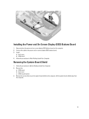
Installing the Power and On-Screen Display (OSD) Buttons Board
1. Align and place the power and on-screen display (OSD) buttons board on the computer. 2. Connect the cable to the power and on-screen display (OSD) buttons board. 3. Install:
a) back cover b) VESA stand 4. Follow the procedures in After Working Inside Your Computer.
Removing the System-Board Shield
1. Follow the procedures in Before ...
Owner's Manual - Page 16
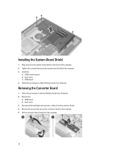
... the system-board shield to the computer. 3. Install the:
a) VESA mount bracket b) back cover c) VESA stand 4. Follow the procedures in After Working Inside Your Computer.
Removing the Converter Board
1. Follow the procedures in Before Working Inside Your Computer. 2. Remove the:
a) VESA stand b) back cover 3. Disconnect the backlight and converter cables from the converter board. 4. Remove the...
Owner's Manual - Page 17
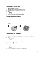
...-cell battery downward until the release latch springs back into place and secures it. 3. Install:
a) system-board shield b) base cover c) VESA stand 4. Follow the procedures in After Working Inside Your Computer.
Removing the Optical Drive
1. Follow the procedures in Before Working Inside Your Computer. 2. Remove the:
a) VESA stand b) back cover 3. Remove the screws that secure the...
Owner's Manual - Page 19
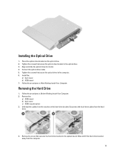
Installing the Optical Drive
1. Place the optical-drive bracket on the optical drive. 2. Tighten the screws that secure the optical-drive bracket to the optical drive. 3. Align and slide the optical drive into its slot. 4. Connect the optical-drive cable. 5. Tighten the screws that secure the optical drive to the computer. 6. Install the:
a) back cover b) VESA stand 7. Follow the procedures in ...
Owner's Manual - Page 20
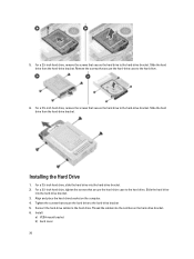
... secure the hard-drive case to the hard drive. Slide the hard drive
into the hard-drive bracket. 3. Align and place the hard-drive bracket on the computer. 4. Tighten the screws that secure the hard drive to the hard-drive bracket 5. Connect the hard-drive cables to the hard drive. Thread the cables into the notches on the hard-drive bracket. 6. Install:
a) VESA mount...
Owner's Manual - Page 22
... the chassis and connect the intrusion-switch cable to the connector on the
system board. 3. Install:
a) system-board shield b) VESA mount bracket c) back cover d) VESA stand 4. Follow the procedures in After Working Inside Your Computer.
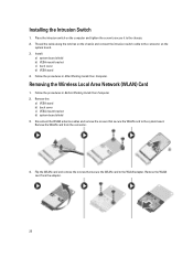
Removing the Wireless Local Area Network (WLAN) Card
1. Follow the procedures in Before Working Inside Your Computer. 2. Remove the:
a) VESA stand b) back cover...
Owner's Manual - Page 23
... secure the WLAN card to the WLAN adapter
2. Place the WLAN card along with the WLAN adapter on its connector and tighten the screws to secure the WLAN card to the system board.
3. Connect the WLAN cables. 4. Install:
a) system-board shield b) VESA mount bracket c) back cover d) VESA stand 5. Follow the procedures in After Working Inside Your Computer.
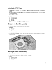
Removing the Heat...
Owner's Manual - Page 44
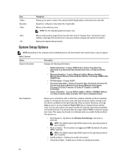
...; PCI Information - Displays SLOT1 • Processor Information - Displays Processor Type, Core Count, Processor ID,
Current Clock Speed, Minimum Clock Speed, Maximum Clock Speed, Processor L2 Cache, Processor L3 Cache, HT Capable, and 64-Bit Technology. • Device Information - Displays SATA-0, SATA-1, SATA-4, LOM MAC Address, and Video Controller Audio Controller, Wi-Fi Device, Bluetooth...
Owner's Manual - Page 49
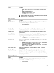
... Option Multi Core Support
Intel SpeedStep C States Control Limited CPUID Value
Intel TurboBoost
Hyper-Thread Control Rapid Start Technology
Table 7. Power Management Option AC Recovery
Description
• Append from File- Adds a key to the current database from a user-selected file
• Delete- Deletes the selected key • Reset All Keys- Resets to default setting • Delete...
Owner's Manual - Page 53
... the log.
• Clear Log
Updating the BIOS
It is recommended to update your BIOS (system setup), on replacing the system board or if an update is available. For laptops, ensure that your computer battery is fully charged and connected to a power outlet
1. Restart the computer. 2. Go to dell.com/support. 3. If you have your computer's Service Tag or Express Service Code:
NOTE: To locate the...