Dell PowerEdge 8450 driver and firmware
Related Dell PowerEdge 8450 Manual Pages
Download the free PDF manual for Dell PowerEdge 8450 and other Dell manuals at ManualOwl.com
Information
Update - Page 3
...) controller • Multiple PowerEdge Expandable RAID Controller II (PERC2) cards and
Dell Diagnostics
• Microprocessor replacement • Microprocessor speed • Operating system clock setting and system event log • Diskette-based diagnostics • Basic input/output system (BIOS) version requirements
Messages and Error Codes
The Dell PowerEdge 8450 Systems Service Manual...
Information
Update - Page 4
... reactivated.
PCI Expansion Cards
When installing expansion cards with the Emergency Management Port (EMP) remote console feature enabled (by pressing during the boot process to enter the BIOS setup), option ROM space is restricted to 64 kilobytes (KB). If the remote console feature is disabled, 80 KB of option ROM space may be used. EMP is not presently supported on the PowerEdge 8450 system...
Information
Update - Page 5
Rack Installation Document
A Dell PowerEdge 8450 Systems Rack Installation Guide is provided with each PowerEdge 8450 rack kit. Use this document to install the system into a rack cabinet. This guide supersedes instructions contained in the Installation and Troubleshooting Guide.
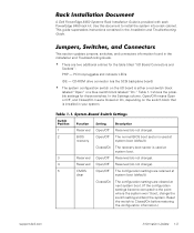
Jumpers, Switches, and Connectors
This section updates jumpers, switches, and connectors information found in the ...
Information
Update - Page 6
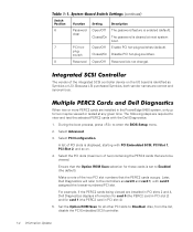
... 0 and card 1, with card 0 assigned the lowest-numbered PCI slot.
For example, if the PERC2 cards being viewed are installed in PCI slots 2 and 4, Dell Diagnostics displays information for card 0 (the PERC2 card in PCI slot 2) and for card 1 (the PERC2 card in PCI slot 4).
5. Set the Option ROM Scan for all other PCI slots to Disabled. Also, from the list, disable the PCI Embedded SCSI controller...
Information
Update - Page 7
...closes freely.
Microprocessor Speed
The Dell PowerEdge 8450 Systems User's Guide states that the system supports microprocessors with an internal operating frequency of 500 MHz. However, it should be noted that microprocessors with internal operating frequencies of 800 MHz or higher are supported.
Setting Microprocessor Speed Jumpers
When changing or upgrading microprocessors, you must verify that...
Information
Update - Page 8
...
Systems with the newer versions of the Intel® Pentium® III microprocessors (700 MHz, 750 MHz, 800 MHz, or higher speeds) require a system setup program BIOS A03 or a later version. If you download and flash an A01 or an A02 BIOS, your system may not operate. To recover a system BIOS, see "Recovering the BIOS" in your Dell PowerEdge 8450 Systems User's Guide.
1-6 Information Update
Installing 1-GB DIMMs
Information Update - Page 3
... for Dell PowerEdge 8450 systems.
The system supports one or two memory boards (see Figure 1-1). The 16 DIMM sockets on each of the system's two memory boards can accommodate up to 16 GB of synchronous dynamic random-access memory (SDRAM). Dell PowerEdge 8450 systems use PC100 systems registered DIMMs in these 168-pin sockets.
J16 J1
support.dell.com
Dell PowerEdge 8450 Systems - Installing 1-GB...
Installing 1-GB DIMMs
Information Update - Page 4
... power supplies from their electrical outlets. 2. Remove the front bezel (see "Checking Inside the Computer" in your system's
Installation and Troubleshooting Guide). 3. To remove the memory board cover, loosen the four captive thumbscrews secur-
ing the memory board cover to the front of the system chassis, and then pull the cover directly away from the system (see Figure 1-2).
1-2 Dell PowerEdge...
Installing 1-GB DIMMs
Information Update - Page 5
... antistatic surface.
5. Locate the DIMM sockets where you will install or replace DIMMs. 6. Install or replace the DIMMs to reach the desired memory total.
To remove a DIMM, press down and outward on the ejectors on each end of the socket until the DIMM disengages from the socket (see Figure 1-3).
support.dell.com
Dell PowerEdge 8450 Systems - Installing 1-GB DIMMs 1-3
Microprocessor Board
Upgrade Guide - Page 5
...1-3 Installing the New Microprocessor Boards 1-12
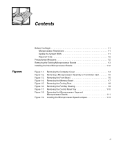
Figure 1-1. Figure 1-2. Figure 1-3. Figure 1-4. Figure 1-5. Figure 1-6. Figure 1-7. Figure 1-8.
Figure 1-9.
Removing the Computer Cover 1-4 Removing a Microprocessor Assembly or Terminator Card 1-5 Removing the Front Bezel 1-6 Removing the Memory Board 1-7 Removing the Cooling Fans 1-8 Removing the Fan Bay Housing 1-9 Removing the Control...
Microprocessor Board
Upgrade Guide - Page 7
... Guide
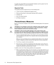
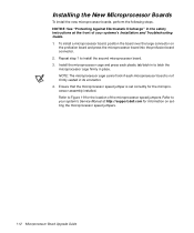
WARNING: The power supplies in this computer system produce high voltages and energy hazards, which can cause bodily harm. Only trained service technicians are authorized to remove the computer cover and access any of the components inside the computer.
This document provides instructions for upgrading the microprocessor boards in your Dell PowerEdge 8450 system to support newer versions...
Microprocessor Board
Upgrade Guide - Page 8
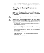
... system yourself, except as explained in this guide and elsewhere in Dell documentation. Always follow installation and service instructions closely. CAUTION: To help avoid possible damage to the system board, wait 5 seconds after turning off the system before removing a component from the system board or disconnecting a peripheral device from the computer.
1. Touch an unpainted metal surface on...
Microprocessor Board
Upgrade Guide - Page 9
... front of your system's Installation and Troubleshooting Guide.
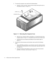
Before working on components inside the system, use a wrist grounding strap for ESD protection.
2. Disconnect all cables from the system.
3. Loosen the thumbscrews on either side of the front bezel that secure the computer to the rack.
4. Slide the computer away from the rack.
support.dell.com
Microprocessor Board Upgrade Guide 1-3
Microprocessor Board
Upgrade Guide - Page 10
... and terminator cards, perform the following steps: a. Using a #2 Phillips screwdriver or your thumbs, loosen the retention screws and release the retaining clip from the microprocessor cage (see steps 1 and 2 in Figure 1-2). b. Using your thumbs, lift the latches on each corner of the microprocessor assembly or terminator card (see step 3 in Figure 1-2).
1-4 Microprocessor Board Upgrade Guide
Microprocessor Board
Upgrade Guide - Page 13
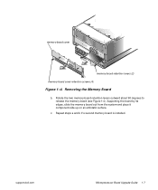
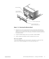
...Removing the Memory Board
b. Rotate the two memory-board retention levers outward about 90 degrees to release the memory board (see Figure 1-4). Supporting the board by its edges, slide the memory board out from the system and place it component-side up on an antistatic surface.
c. Repeat steps a and b if a second memory board is installed.
support.dell.com
Microprocessor Board Upgrade Guide 1-7
Microprocessor Board
Upgrade Guide - Page 14
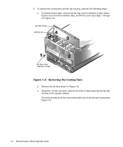
... bay cover cooling fan
fan bay cover retention screw
Figure 1-5. Removing the Cooling Fans
b. Remove the six fans (step 4 in Figure 1-5). c. Using the 1/4-inch nut driver, remove the three screws securing the fan bay
housing to the system chassis. The three screws are at the front and at each end of...
Microprocessor Board
Upgrade Guide - Page 16
...
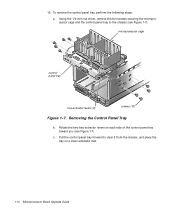
control panel tray
tray extractor levers (2)
screws (10)
Figure 1-7. Removing the Control Panel Tray
b. Rotate the two tray extractor levers on each side of the control panel tray toward you (see Figure 1-7).
c. Pull the control panel tray forward to clear it from the chassis, and place the tray on a clean antistatic mat.
1-10 Microprocessor Board Upgrade Guide
Microprocessor Board
Upgrade Guide - Page 18
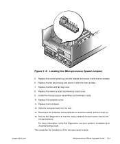
... board is not firmly seated in its connector. 4. Ensure that the microprocessor speed jumper is set correctly for the microprocessor assembly installed. Refer to Figure 1-9 for the location of the microprocessor speed jumpers. Refer to your system's Service Manual at http://support.dell.com for information on setting the microprocessor speed jumpers.
1-12 Microprocessor Board Upgrade Guide
Microprocessor Board
Upgrade Guide - Page 19
support.dell.com
Figure 1-9. Locating the Microprocessor Speed Jumpers
5. Replace the control panel tray into the chassis and secure it with the ten screws. 6. Replace the fan bay housing and secure it with the three screws. 7. Replace the fans and fan bay cover. 8. Replace the memory board and memory board cover. 9. Install the microprocessor assemblies and terminator cards. 10. Replace...
Rack Installation Guide - Page 139
...: EMAIL ADDRESS: VENDOR: DATE:
Dell PowerEdge 8450 Systems Rack Instalation Guide (s:\systems\diamond\TWR\Rack_Guide)
English, French, German Spanish
9561T Rev. A00 Empact: yes at A00
Adams Translations (Tammy Lang)
Judy Runyan
Donna Moore
512-728-3439
donna_moore@dell.com
Copyright/EMF
8/17/99
COMPUTER SOURCE:
Dell PC
APPLICATION SOFTWARE:
FrameMaker
Version 5.5.2
POSTSCRIPT...