Dell Precision T1700 driver and firmware

Related Dell Precision T1700 Manual Pages
Download the free PDF manual for Dell Precision T1700 and other Dell manuals at ManualOwl.com
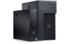
Owner's Manual - Mini Tower - Page 2
... Dell Inc. Intel®, Pentium®, Xeon®, Core® and Celeron® are registered trademarks of Intel Corporation in the U.S. and other countries. AMD® is a registered trademark and AMD Opteron™, AMD Phenom™ and AMD Sempron™ are trademarks of Advanced Micro Devices, Inc. Microsoft®, Windows®, Windows Server®, Internet...
Owner's Manual - Mini Tower - Page 3
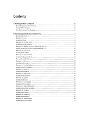
... Installing the Wireless Local Area Network (WLAN) Card 10 Removing the Front Bezel...10 Installing the Front Bezel...10 Removing the Expansion Card...10 Installing the Expansion Card...11 Memory Module Guidelines...11 Removing the Memory...12 Installing the Memory...12 Removing the Coin-Cell Battery...12 Installing the Coin-Cell Battery...13 Removing the Hard Drive...13 Installing the Hard Drive...
Owner's Manual - Mini Tower - Page 4

... the Power Switch...23 Removing the Input/Output (I/O) Panel...24 Installing the Input/Output (I/O) Panel...25 Removing the System Board...25 System Board Components...26 Installing the System Board...27
3 Using The System Setup Program And Boot Manager 29
Boot Sequence...29 Navigation Keys...29 System Setup Options...30 Updating the BIOS ...38 Jumper Settings...39 System and Setup Password...39...
Owner's Manual - Mini Tower - Page 5
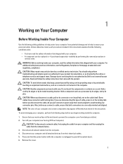
... Off Your Computer).
CAUTION: To disconnect a network cable, first unplug the cable from your computer and then unplug the cable from the network device. 3. Disconnect all network cables from the computer. 4. Disconnect your computer and all attached devices from their electrical outlets. 5. Press and hold the power button while the computer is unplugged to ground the system board. 6. Remove the...
Owner's Manual - Mini Tower - Page 6
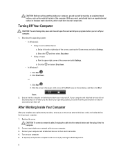
... system, press and hold the power button for about 6 seconds to turn them off.
After Working Inside Your Computer
After you complete any replacement procedure, ensure you connect any external devices, cards, and cables before turning on your computer.
1. Replace the cover. CAUTION: To connect a network cable, first plug the cable into the network device and then plug it into the...
Owner's Manual - Mini Tower - Page 7
... information on how to remove or install the components from your computer.
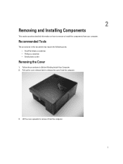
Recommended Tools
The procedures in this document may require the following tools: • Small flat-blade screwdriver • Phillips screwdriver • Small plastic scribe
Removing the Cover
1. Follow the procedures in Before Working Inside Your Computer. 2. Pull up the cover release...
Owner's Manual - Mini Tower - Page 8
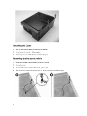
... cover till it clicks into place. 3. Follow the procedures in After Working Inside Your Computer.
Removing the Intrusion Switch
1. Follow the procedures in Before Working Inside Your Computer. 2. Remove the cover. 3. Disconnect the intrusion-switch cable from the system board. 4. Slide the intrusion switch toward the bottom of the chassis and remove it from...
Owner's Manual - Mini Tower - Page 9
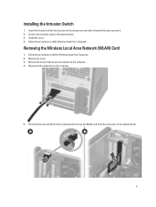
... and slide it towards the top to secure it. 2. Connect the intrusion cable to the system board. 3. Install the cover. 4. Follow the procedures in After Working Inside Your Computer.
Removing the Wireless Local Area Network (WLAN) Card
1. Follow the procedures in Before Working Inside Your Computer. 2. Remove the cover. 3. Remove the screws that secure the antenna to the...
Owner's Manual - Mini Tower - Page 10
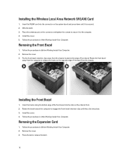
Installing the Wireless Local Area Network (WLAN) Card
1. Insert the WLAN card into the connector on the system board and press down until it is secured. 2. Affix the latch. 3. Place the antenna puck on the connector and tighten the screws to secure it to the computer. 4. Install the cover. 5. Follow the procedures in After Working Inside Your Computer.
Removing the...
Owner's Manual - Mini Tower - Page 11
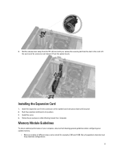
... its connector and remove it from the system board.
Installing the Expansion Card
1. Insert the expansion card in the connector on the system board and press down until secured. 2. Push the retention latch back to its position. 3. Install the cover. 4. Follow the procedures in After Working Inside Your Computer.
Memory Module Guidelines
To ensure optimal performance of your...
Owner's Manual - Mini Tower - Page 12
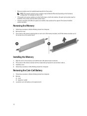
... speed of the slowest installed memory modules.
Removing the Memory
1. Follow the procedures in Before Working Inside Your Computer. 2. Remove the cover. 3. Press down on the memory retaining tabs on each side of the memory modules, and lift the memory modules out of
the connectors on the system board.
Installing the Memory
1. Align the notch on the memory-card with the tab...
Owner's Manual - Mini Tower - Page 13
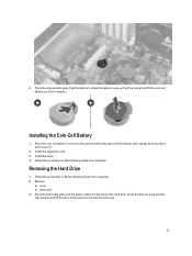
... on the system board and press until the release latch springs back into place and secures it.
2. Install the expansion card. 3. Install the cover. 4. Follow the procedures in After Working Inside Your Computer.
Removing the Hard Drive
1. Follow the procedures in Before Working Inside Your Computer. 2. Remove:
a) cover b) front bezel 3. Disconnect the data cable and the power cable from the...
Owner's Manual - Mini Tower - Page 35
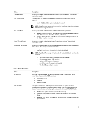
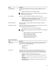
...; Memory capacity over 8GB installed. • System or HDD password is enabled • A Dell Encryption Accelerator is installed • The Block Sleep setting is enabled
Description Specifies how the computer will respond when AC power is applied after an AC power loss. You can set the AC Recovery to:
• Power Off (default) • Power On • Last Power State
This option sets the...
Owner's Manual - Mini Tower - Page 39
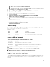
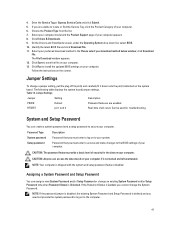
... Download window appears. 12. Click Save to save the file on your computer. 13. Click Run to install the updated BIOS settings on your computer. Follow the instructions on the screen.
Jumper Settings
To change a jumper setting, pull the plug off its pin(s) and carefully fit it down onto the pin(s) indicated on the system
board. The following table displays the system board jumper settings...
Owner's Manual - Mini Tower - Page 44
...Re-install the memory
memory
modules and, if necessary, replace them.
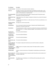
Diskette drive 0 seek A cable may be loose or the computer configuration information may not match the hardware
failure
configuration.
Diskette read failure The floppy disk may be defective or a cable may be loose. If the drive access light turns on, try a different disk.
Diskette subsystem The floppy drive controller may...
Owner's Manual - Small Form Factor - Page 4
... Assembly...27 Removing the Processor...27 Installing the Processor...28 System Board Components...28 Removing the System Board...29 Installing the System Board...29
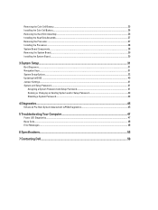
3 System Setup...31
Boot Sequence...31 Navigation Keys...31 System Setup Options...32 Updating the BIOS ...40 Jumper Settings...41 System and Setup Password...41
Assigning a System Password and Setup Password 41 Deleting or Changing...
Owner's Manual - Small Form Factor - Page 37
...; Memory capacity over 8GB installed. • System or HDD password is enabled • A Dell Encryption Accelerator is installed • The Block Sleep setting is enabled
Description Specifies how the computer will respond when AC power is applied after an AC power loss. You can set the AC Recovery to:
• Power Off (default) • Power On • Last Power State
This option sets the...
Owner's Manual - Small Form Factor - Page 41
... Download window appears. 12. Click Save to save the file on your computer. 13. Click Run to install the updated BIOS settings on your computer. Follow the instructions on the screen.
Jumper Settings
To change a jumper setting, pull the plug off its pin(s) and carefully fit it down onto the pin(s) indicated on the system
board. The following table displays the system board jumper settings...
Owner's Manual - Small Form Factor - Page 48
... and power system.
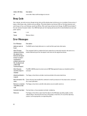
Code Cause
1-3-2 Memory failure
Error Messages
Error Message
Description
Address mark not found
The BIOS found a faulty disk sector or could not find a particular disk sector.
Alert! Previous attempts at booting this system have failed at checkpoint [nnnn]. For help in resolving this problem, please note this checkpoint and contact Dell Technical Support.
The computer...
Owner's Manual - Small Form Factor - Page 49
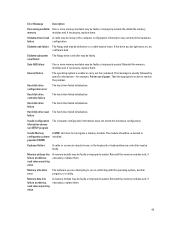
...Re-install the memory
memory
modules and, if necessary, replace them.
Diskette drive 0 seek A cable may be loose or the computer configuration information may not match the hardware
failure
configuration.
Diskette read failure The floppy disk may be defective or a cable may be loose. If the drive access light turns on, try a different disk.
Diskette subsystem The floppy drive controller may...