Foxconn G41MD-V driver and firmware
Related Foxconn G41MD-V Manual Pages
Download the free PDF manual for Foxconn G41MD-V and other Foxconn manuals at ManualOwl.com
English Manual - Page 5
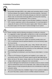
... the
computer if the CPU fan is not properly installed.
■ We cannot guarantee that your system can operate normally when your
CPU is overclocked. Normal operation depends on the overclocking capac-
ity of your device.
■ If there is any, when connecting USB, audio, 1394a, RS232 COM, IrDA or
S/PDIF cables to the internal connectors on the motherboard...
English Manual - Page 6
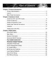
... and CPU Cooler 8 Install the Memory 11 Install an Expansion Card 13 Install other Internal Connectors 14 Jumpers 17
Install driver and utility 20 Chapter 3 BIOS Setup
Enter BIOS Setup 23 Main Menu 23 System Information 25 Advanced BIOS Features 27 ......F.o.x..C.e.n.tr.a.l.C.o.n.t.ro.l.U..n.it 29 ......A.d.v.a.n.ce.d..C.h.ip.s.e.t.F.e.a.tu.r.e.s 33 Integrated Peripherals 36 Power...
English Manual - Page 10
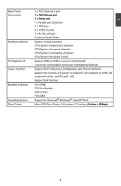
... x Parallel port (optional) 1 x VGA port 4 x USB 2.0 ports� 1 x RJ-45 LAN port 6-channel Audio Ports
Hardware Monitor
System voltage detection
CPU/System temperature detection
CPU/System fan speed detection
CPU/System overheating shutdown
CPU/System fan speed control
PCI Express x16 Support 8GB/s (16GB/s concurrent) bandwidth Low power consumption and power management...
English Manual - Page 14
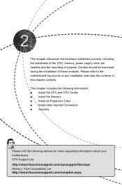
... includes the following information : ■ Install the CPU and CPU Cooler ■ Install the Memory ■ Install an Expansion Card ■ Install other Internal Connectors ■ Jumpers
Please visit the following website for more supporting information about your motherboard. CPU Support List: http://www.foxconnsupport.com/cpusupportlist.aspx Memory, VGA Compatibility List: http://www...
English Manual - Page 15
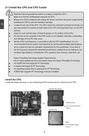
... card, memory, hard drive, etc.
Hyper-Threading Technology System Requirements: (Go to Intel's website for more information about the Hyper-Threading Technology) ■ An Intel® CPU that supports HT Technology ■ A chipset that supports HT Technology ■ An operating system that is optimized for HT Technology ■ A BIOS that supports HT Technology and has it enabled
Install...
English Manual - Page 16
CAUTION
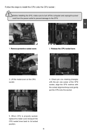
Follow the steps to install the CPU onto the CPU socket :
! Before installing the CPU, make sure to turn off the computer and unplug the power
cord from the power outlet to prevent damage to the CPU.
2
1. R��e�m��o�v�e��p�r�o�t�e�c�t�iv�e��s�o&#...
English Manual - Page 17
...
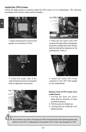
Follow the steps below to correctly install the CPU cooler on the motherboard. (The following
procedures use Foxconn cooler as the example.)
2
CAUTION
1. Apply and spread an even thermal grease on the surface of CPU.
2. Place the four bolts of the CPU cooler to the holes of the motherboard, push them straight down from the top, and...
English Manual - Page 18
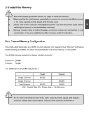
... you begin to install the memory : ■ Make sure that the motherboard supports the memory. It is recommended that memory
of the same capacity, brand, speed, and chips be used. ■ Always turn off the computer and unplug the power cord from the power outlet before
installing the memory to prevent hardware damage. ■ Memory modules have a foolproof design. A memory module can be...
English Manual - Page 19
2 CAUTION
144-Pin
96-Pin
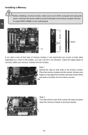
Installing a Memory
! Before installing a memory module, make sure to turn off the computer and unplug the power cord from the power outlet to prevent damage to the memory module. Be sure to install DDR3 DIMMs on this motherboard.
Notch
If you take a look at front side of memory module, it has asymmetric pin counts on both sides...
English Manual - Page 20
...2
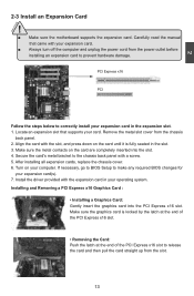
2-3 Install an Expansion Card
!
■ Make sure the motherboard supports the expansion card. Carefully read the manual that came with your expansion card.
■ Always turn off the computer and unplug the power cord from the power outlet before installing an expansion card to prevent hardware damage.
PCI Express x16
PCI
Follow the steps below to correctly install your expansion card in the...
English Manual - Page 21
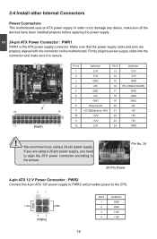
... order not to damage any device, make sure all the devices have been installed properly before applying the power supply.
24-pin ATX Power Connector : PWR1 PWR1 is the ATX power supply connector. Make sure that the power supply cable and pins are properly aligned with the connector on the motherboard. Firmly plug the power supply cable into the connector and...
English Manual - Page 27
2
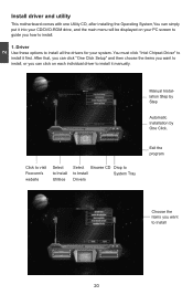
Install driver and utility
This motherboard comes with one Utility CD, after installing the Operating System,You can simply put it into your CD/DVD-ROM drive, and the main menu will be displayed on your PC screen to guide you how to install.
1. Driver Use these options to install all the drivers for your system. You must click "Intel Chipset Driver" to install it first...
English Manual - Page 28
2
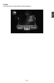
2. Utility Use these options to install additional software programs.
21 21
English Manual - Page 29
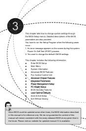
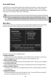
... the following cases occur : 1. An error message appears on the screen during the system
Power On Self Test (POST) process. 2. You want to change the default CMOS settings.
This chapter includes the following information : ■ Enter BIOS Setup ■ Main Menu ■ System Information ■ Advanced BIOS Features ■ Fox Central Control Unit ■ �A�d�...
English Manual - Page 30
...: ► System Information
It displays the basic system configuration, such as BIOS version, CPU Name, memory size plus system date, time. They all can be viewed or set up through this menu. ► Advanced BIOS Features The advanced system features can be set up through this menu. There are boot up settings. ► Fox Central Control Unit Some special proprietary...
English Manual - Page 31
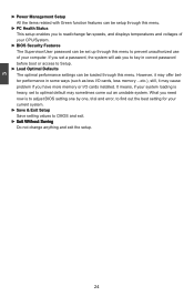
... if you have more memory or I/O cards installed. It means, if your system loading is heavy, set to optimal default may sometimes come out an unstable system. What you need now is to adjust BIOS setting one by one, trial and error, to find out the best setting for your current system.
► Save & Exit Setup Save setting values to CMOS...
English Manual - Page 33

3
Model name of this product. ► BIOS Version
It displays the current BIOS version. User can check this information and discuss with the field service people if a BIOS upgrade is needed. ► Memory This item shows the information of the system memory, determined by POST(Power On Self Test) of the BIOS. ► MAC Address This item shows the onboard LAN MAC address.
26
English Manual - Page 38
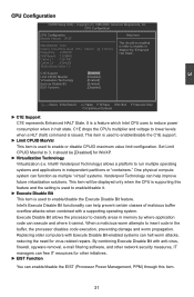
...compute system can function as multiple "virtual" systems. Vanderpool Technology can help improve future virtualization solutions. This item will be displayed only when the CPU is supporting this feature and the setting... software, and other network security measures, IT managers can free IT resources for other initiatives.
► EIST Function
You can enable/disable the EIST (Processor Power ...
English Manual - Page 41
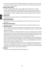
... important information about the module's speed, size, addressing mode and various other parameters, so that the motherboard memory controller (chipset) can better access the memory device. ► Memory Hole This item is used to determine whether the 15M-16M address field of memory is reserved for the ISA expansion card. ► Initate Graphic Adapter This item is used to choose the initate...
English Manual - Page 51
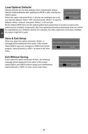
... of system components. But if the optimal performance parameters to be set cannot
be supported by your hardware devices (for example, too many expansion cards were installed),
the system might fail to work.
Save & Exit Setup
When you select this option and press , a message will be displayed in the center of the screen: Select [OK] to save...