Gigabyte C7V7-CSI driver and firmware

Related Gigabyte C7V7-CSI Manual Pages
Download the free PDF manual for Gigabyte C7V7-CSI and other Gigabyte manuals at ManualOwl.com
Manual - Page 2
... Standard CMOS Features 22 2-2 Advanced BIOS Features 24 2-3 Advanced Chipset Features 27 2-3 IntegratedPeripherals 33 2-4 Power Management Setup 37 2-5 PnP/PCI Configurations 41 2-6 PC Health Status 42 2-7 Frequency / Voltage Control 43 2-8 Load Fail-Safe Defaults 44 2-9 Load Optimized Defaults 44 2-10 Set Supervisor/User Password 45 2-11 Save & Exit Setup 46 2-12 Exit Without Saving...
Manual - Page 5
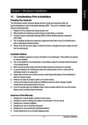
...: 1. Please turn off the computer and unplug its power cord. 2. When handling the motherboard, avoid touching any metal leads or connectors. 3. It is best to wear an electrostatic discharge (ESD) cuff when handling electronic components
(CPU, RAM). 4. Prior to installing the electronic components, please have these items on top of an antistatic pad or
within a electrostatic...
Manual - Page 6
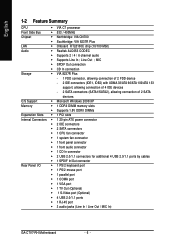
... of 2 SATA
devices
O.S Support
Š Microsoft Windows 2000/XP
Memory
Š 1 DDRII DIMM memory slots
Š Supports 1.8V DDRII DIMMs
Expanstion Slots Š 1 PCI slots
Internal Connectors Š 1 20-pin ATX power connector
Š 2 IDE connectors
Š 2 SATA connectors
Š 1 CPU fan connector
Š 1 system fan connector
Š 1 front panel connector
Š 1 front audio...
Manual - Page 7
English
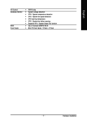
I/O Control Hardware Monitor
BIOS Form Factor
Š IT8712 chip Š System voltage detection Š CPU / System temperature detection Š CPU / System fan speed detection Š CPU warning temperature Š CPU / System fan failure warning Š Supports CPU / System Smart Fan function Š Use of licensed AWARD BIOS Š Mini-ITX form factor; 17.0cm x 17.0cm
- 7 -
...
Manual - Page 8
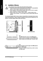
... that the computer
power is switched off to prevent hardware damage. 3. Memory modules have a foolproof insertion design. A memory module can be
installed in only one direction. If you are unable to insert the module, please switch the direction. The motherboard supports DDR II memory modules, whereby BIOS will automatically detect memory capacity and specifications. Memory modules are designed...
Manual - Page 9
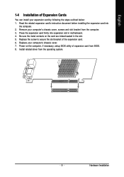
... from the computer. 3. Press the expansion card firmly into expansion slot in motherboard. 4. Be sure the metal contacts on the card are indeed seated in the slot. 5. Replace the screw to secure the slot bracket of the expansion card. 6. Replace your computer's chassis cover. 7. Power on the computer, if necessary, setup BIOS utility of expansion card from BIOS. 8. Install related driver from the...
Manual - Page 10
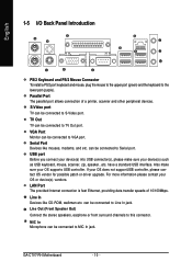
.... Also make sure your OS supports USB controller. If your OS does not supportUSB controller, please contact OS vendor for possible patch or driver upgrade. For more information please contact your OS or device(s) vendors. LAN Port The provided Internet connection is fast Ethernet, providing data transfer speeds of 10/100Mbps.
Line In Devices like CD-ROM, walkman etc. can be connected to...
Manual - Page 11
English
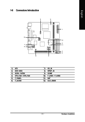
1-6 Connectors Introduction
9
5
1
10
12
2
7
11
6
4 5
8
3
1) ATX 2) IDE1/ IDE2 3) SATA1 / SATA2 4) CPU_FAN / SYS_FAN 5) F_PANEL 6) F_AUDIO
7) CD_IN 8) SPDIF_IO 9) COMB 10) F_USB1 / F_USB2 11) BAT 12) CLR_CMOS
- 11 -
Hardware Installation
Manual - Page 12
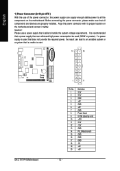
... (2x10 pin ATX )
With the use of the power connector, the power supply can supply enough stable power to all the components on the motherboard. Before connecting the power connector, please make sure that all components and devices are properly installed. Align the power connector with its proper location on the motherboard and connect it tightly. Caution! Please use...
Manual - Page 13
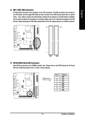
... information on settings, please refer to the instructions located on the IDE device). Before attaching the IDE cable, please take note of the foolproof groove in the IDE connector.
40
39
2 IDE1
1 IDE2
3) SATA1/SATA2 (Serial ATA Connector,) Serial ATA can provide up to 150MB/s transfer rate. Please refer to the BIOS setting for the Serial ATA and install the proper driver in order...
Manual - Page 15
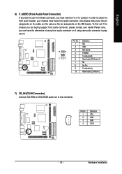
...audio connector or of using rear audio connector to play sound.
10
9
2
1
Pin No. 1 2 3 4 5 6 7 8 9 10
Definition MIC GND MIC_BIAS POWER FrontAudio(R) Rear Audio (R)/ Return R NC No Pin FrontAudio (L) Rear Audio (L)/ Return L
7) CD_IN (CD IN Connector) Connect CD-ROM or DVD-ROM audio out to the connector.
Pin No. Definition
1
CD-L
1
2
GND
3
GND
4
CD-R
- 15 -
Hardware Installation
Manual - Page 17
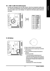
... pin assignment carefully while you connect the front USB cable, incorrect connection between the cable and connector will make the device unable to work or even damage it. For optional front USB cable, please contact your local dealer.
9
1
10
2
Pin No. 1 2 3 4 5 6 7 8 9 10
Definition Power (5V) Power (5V) USB DXUSB DyUSB DX+ USB Dy+ GND GND No Pin NC
11) BAT...
Manual - Page 19
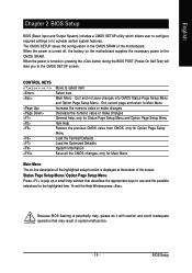
... configuration in the CMOS SRAM of the motherboard. When the power is turned off, the battery on the motherboard supplies the necessary power to the CMOS SRAM. When the power is turned on, pressing the button during the BIOS POST (Power-On Self Test) will take you to the CMOS SETUP screen.
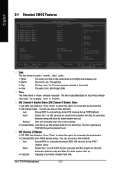
CONTROL KEYS Enter>
Move to select item...
Manual - Page 22
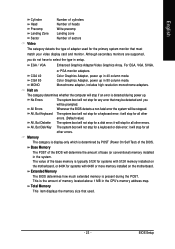
... IDE Drive SATA devices setup. You can use one of two methods:
Auto
Allows BIOS to automatically detect SATA IDE devices during POST.
(Default value)
None
Select this if no SATA IDE devices are used and the system will skip the
automatic detection step and allow for faster system start up.
Capacity
Capacity of currently installed hard disk.
GA-C7V7-RH Motherboard
- 22...
Manual - Page 23
... typically 512K for systems with 512K memory installed on the motherboard, or 640K for systems with 640K or more memory installed on the motherboard.
Extended Memory
The BIOS determines how much extended memory is present during the POST. This is the amount of memory located above 1 MB in the CPU's memory address map. Total Memory
This item displays the memory size that used.
- 23 -
BIOS Setup
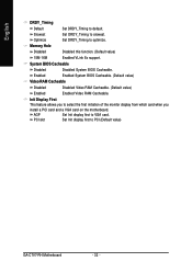
Manual - Page 25
... flash tools can
update BIOS always.
CPU L1 & L2 Cache
These two categories speed up memory access. However, it depends on CPU / chipset design.
Enabled
Enabled Cache.(Default Value)
Disabled
Disalbed Cache.
CPU L2 Cache ECC Checking
Enabled
Enabled CPU L2 Cache ECC Checking.(Default Value)
Disabled
Disalbed CPU L2 Cache ECC Checking.
Quick Power On Self Test
If it is set...
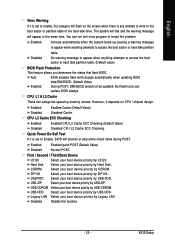
Manual - Page 32
...
Disabled Video RAM Cacheable. (Default value)
Enabled
Enabled Video RAM Cacheable.
Init Display First
This feature allows you to select the first initiation of the monitor display from which card when you
install a PCI card and a VGA card on the motherboard.
AGP
Set Init display first to VGA card.
PCI slot
Set Init display first to PCI.(Default value)
GA-C7V7-RH Motherboard
- 32...
Manual - Page 41
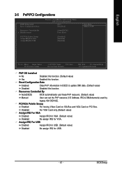
... (Default value)
Disabled
Disabled this function.
Resources Controlled By
Auto(ESCD)
BIOS automatically use these PnP rescuers. (Default value)
Manual
User can set the PnP resource (I/O Address, IRQ & DMAchannels) used by
legacy ISA DEVICE.
PCI/VGA Palette Snoop
Enabled
For having Video Card on ISA Bus and VGA Card on PCI Bus.
Disabled
For VGA Card only.(Default value)
Assign IRQ For...