Gigabyte GA-2AIEV-RH driver and firmware
Drivers and firmware downloads for this Gigabyte item

Related Gigabyte GA-2AIEV-RH Manual Pages
Download the free PDF manual for Gigabyte GA-2AIEV-RH and other Gigabyte manuals at ManualOwl.com
Manual - Page 2
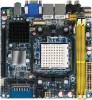
GA-2AIEV-RH/GA-2AIEV2-RH/GA-2AIEV3-RH Motherboard Copyright © 2008 GIGA-BYTE TECHNOLOGY CO., LTD. All rights reserved. The trademarks mentioned in the manual are legally registered to their respective companies.
Notice The written content provided with this product is the property of Gigabyte. No part of this manual may be reproduced, copied, translated, or transmitted in any form or...
Manual - Page 3
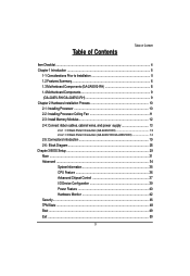
...2-3: Install Memory Modules 12 2-4: Connect ribbon cables, cabinet wires, and power supply 13
2-4-1 : I/O Back Panel Introduction (GA-2AIEV2-RH 13 2-4-2 : I/O Back Panel Introduction (GA-2AIEV-RH/GA-2AIEV3-RH 14
2-5: Connectors Introduction 19 2-6: Block Diagram 28 Chapter 3 BIOS Setup 29 Main ...31 Advanced ...34
SystemInformation 35 CPU Feature 36 Advanced Chipset Control 37 I/O Device...
Manual - Page 4
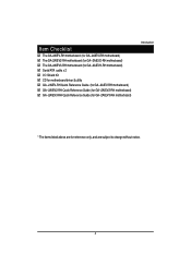
... GA-2AIEV-RH motherboard (for GA--2AIEV-RH motherboard) The GA-2AIEV2-RH motherboard (for GA--2AIEV2-RH motherboard) The GA-2AIEV3-RH motherboard (for GA--2AIEV3-RH motherboard) Serial ATA cable x 2 I/O Shield Kit CD for motherboard driver & utility GA--2AIEV-RH Quick Reference Guide (for GA--2AIEV-RH motherboard) GA--2AIEV2-RH Quick...
Manual - Page 5
GA-2AIEV-RH/GA-2AIEV2-RH/GA-2AIEV3-RH Motherboard
Chapter 1 Introduction
1-1 Considerations Prior to Installation
Preparing Your Computer The motherboard contains numerous delicate electronic circuits and components which can become damaged as a result of electrostatic discharge (ESD). Thus, prior to installation, please follow the instructions below: 1. Please turn off the computer and unplug its...
Manual - Page 7
GA-2AIEV-RH/GA-2AIEV2-RH/GA-2AIEV3-RH Motherboard
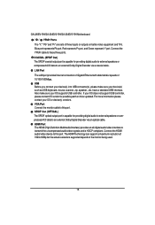
4 x USB 2.0 ports
2 x LAN RJ45 ports
1 HD Audio jacks (Line-out / MIC-in / Line-in) can configure 5.1
channel output by utility
**Note** SPDIF Out (Optical + Coaxial) device only for GA-2AIEV2-RH
Hardware Monitor
Enhanced features with CPU Vcore, 1.5V reference,
VCC3 (3.3V) , VBAT3V, +5VSB, CPUA/B ...
Manual - Page 10
Hardware Installation Process
Chapter 2 Hardware Installation Process
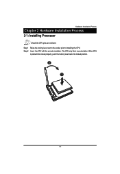
2-1: Installing Processor
Check the CPU pins are not bent. Step 1 Raise the locking lever next to the socket prior to installing the CPU. Step 2 Insert the CPU with the correct orientation. The CPU only fits in one orientation. When CPU
is placed into socket properly, push the locking lever back into locked position.
2 1
10
Manual - Page 11
GA-2AIEV-RH/GA-2AIEV2-RH/GA-2AIEV3-RH Motherboard
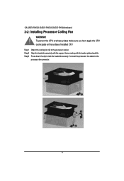
2-2: Installing Processor Colling Fan
WARNING!
㕑
To prevent the CPU overheat, please make sure you have apply the CPU cooler paste on the surface of installed CPU
Step 1 Attach the cooling fan clip to the processor scoket. Step 2 Align the heatsink assembly with the support frame mating with the backer plate standoffs. Step 3 Press down ...
Manual - Page 12
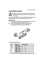
..., please comply with the following conditions: 1. Please make sure the computer power is switched off before installing or removing
memory modules.
The motherboard supports DDR2 memory module, whereby BIOS will automatically detect memory capacity and specifications. The memory module only can be inserted in one direction.
Installation Steps: Step 1. Unlock a DIMM socket by pressing the retaining...
Manual - Page 15
... support USB controller, please contact OS vendor for possible patch or driver updated. For more information please contact your OS or device(s) vendors. VGA Port Connect the monitor cable to this port. SPDIF Out (OPTICAL) The SPDIF optical output port is capable for providing digital audio to external speakers or compressed AC3 data to an external Dolby Digital Decoder via an optical cable. HDMI...
Manual - Page 16
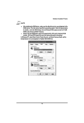
... for details.), and enter BIOS Setup, then set Onboard VGA output connect to D-SUB/ HDMI under Advanced BIOS Features. Please note the HDMI audio output only supports AC3, DTS and 2-channel-LPCM formats. (AC3 and DTS require the use of an external decoder for decoding.) In Windows XP, select Start>Control Panel>Sounds and Audio Devices>Audio, set the Default device for sound playback to...
Manual - Page 17
GA-2AIEV-RH/GA-2AIEV2-RH/GA-2AIEV3-RH Motherboard In Windows Vista, select Start>Control Panel>Sound, select Realtek HDMI Output and then click Set Default.
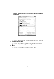
Line In The default Line In jack. Devices like CD-ROM, walkman etc. can be connected to Line In jack. Line Out (Front Speaker Out) The default Line Out (Front Speaker Out) jack. Stereo speakers, earphone ...
Manual - Page 18
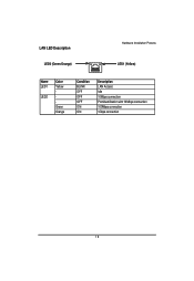
LAN LED Description LED2 (Green/Orange)
Hardware Installation Process LED1 (Yellow)
Name LED1
LED2
Color Yellow Green Orange
Condition BLINK OFF OFF OFF ON ON
Description LAN Access Idle 10Mbps connection Port identification with 10 Mbps connection 100Mbps connection 1Gbps connection
18
Manual - Page 20
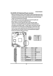
... sure that
all components and devices are properly installed. Align the power connector with its proper
location on the motherboard and connect tightly.
The ATX_12V power connector mainly supplies power to the CPU. If the ATX_12V
power connector is not connected, the system will not start.
Caution! Please use a power supply that is able to support the system voltage
requirements...
Manual - Page 21
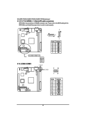
GA-2AIEV-RH/GA-2AIEV2-RH/GA-2AIEV3-RH Motherboard 3/ 4/ 5/ 6/ 7/ 8 ) SATAII0_1~6 (Serial ATA cable connectors)
SATA 3Gb/s can provide up to 300MB/s stransfer rate. Please refer to the BIOS setting for the SATA 3Gb/s and install the proper driver in order to work properly.
7
7
1
SATA4 SATA3 SATA2 SATA1
1
Pin No.
1 2 3 4 5 6 7
Definition
GND TXP TXN GND RXN RXP GND
SATA5 SATA6
9/ 10 ) COMA1/...
Manual - Page 25
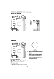
GA-2AIEV-RH/GA-2AIEV2-RH/GA-2AIEV3-RH Motherboard 18 ) LPC (LPC connector)
21
Pin No. Definition
1
FWH33
2
-A_RST
3
-LFRAME
10 9
4
LAD3
5
LAD2
6... batteries according to the
manufacturer's instructions. If you want to erase CMOS... 1.Turn OFF the computer and unplug the power cord. 2.Remove the battery, wait for 30 second. 3.Re-install the battery. 4.Plug the power cord and turn ON the...
Manual - Page 27
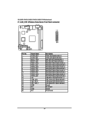
GA-2AIEV-RH/GA-2AIEV2-RH/GA-2AIEV3-RH Motherboard 21 ) LED_CON (Windows Home Server Front Panel connector)
12
1920
Pin No. 1. 2. 3. 4. 5. 6. 7. 8. 9. 10. 11. 12. 13. 14. 15. 16. 17. 18. 19. 20.
Signal Name Power LED+ Power LEDBOOT_LED+ BOOT_LEDHDD1_LED+ HDD1_LEDHDD2_LED+ HDD2_LEDHDD2_LED+ HDD3_LEDHDD4_LED+ HDD4_LEDL12 LINK_LEDLED_100_P LED_1000_P GND NC GND NC
Description Power LED Signal ...
Manual - Page 30
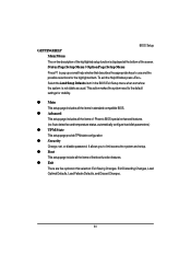
.... To exit the Help Window press . Select the Load Setup Defaults item in the BIOS Exit Setup menu when somehow the system is not stable as usual. This action makes the system reset to the default settings for stability.
z Main This setup page includes all the items in standard compatible BIOS.
z Advanced This setup page includes all the items...
Manual - Page 32
BIOS Setup
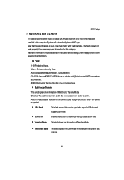
Slave/SATA Port 1/2/3/4/5/6
The category identifies the types of Serial SATA hard disk from drive 1 to 6 that has been installed in the computer. System will automatically detect HDD type. Note that the specifications of your drive must match with the drive table. The hard disk will not work properly if you enter improper information for this category. Hard drive information should be ...
Manual - Page 33
... all other errors. (Default setting)
All Errors
Whenever the BIOS detects a non-fatal error the system will be stopped.
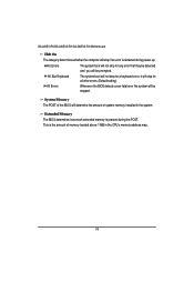
System Memory The POST of the BIOS will determine the amount of system memory installed in the system.
Extended Memory The BIOS determines how much extended memory is present during the POST. This is the amount of memory located above 1 MB in the CPU's memory address map...
Manual - Page 35
GA-2AIEV-RH/GA-2AIEV2-RH/GA-2AIEV3-RH Motherboard
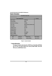
System Information
PhoenixBIOS Setup Utility
Advanced
System Management
Item Help
BIOS Version:
2AIEV-E5a
Product Name:
Bluefin
BIOS Date (mm/dd/yy)
12/09/08
CPU Type
AMD Phenom(tm) 9350e Quad
CPU Speed
200MHz
AGESA Version:
03.01.09
NB CIM Version:
4.3.0
SB CIM Version:
4.0.0
Memory DIMM1:
Not Installed
Memory DIMM2:
...