Gigabyte GA-3CESL3-RH driver and firmware
Drivers and firmware downloads for this Gigabyte item

Related Gigabyte GA-3CESL3-RH Manual Pages
Download the free PDF manual for Gigabyte GA-3CESL3-RH and other Gigabyte manuals at ManualOwl.com
Manual - Page 2
...Summary 4 1.2 GA-3CESL3-RH Motherboard Components 6 Chapter 2 Hardware Installation Process 8 2-1: Installing Processor and CPU Haet Sink 8
2-1-1: Installing CPU ...8 2-1-2: Installing Heat Sink 9
2-2: Install Memory Modules 10 2-3: Connect ribbon cables, cabinet wires, and power supply 13
2-3-1 : I/O Back Panel Introduction 13
2-4: Connectors Introduction 15 Chapter 3 BIOS Setup 27
Main...
Manual - Page 3
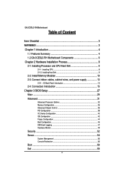
Item Checklist
GA-3CESL3-RH motherboard Serial ATA cable x 6 IDE (ATA133 ) cable x 1 / Floppy cable x 1 CD for motherboard driver & utility
Introduction
GA-3CESL3-RH Quick Reference Guide I/O Shield Kit SATA Power cable x 3
WARNING!
Computer motherboards and expansion cards contain very delicate Integrated Circuit (IC) chips. To protect them against damage from static electricity, you should ...
Manual - Page 4
...
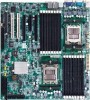
GA-3CESL3-RH Motherboard
Chapter 1 Introduction
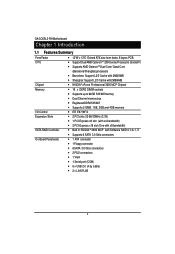
1.1 Features Summary
Form Factor CPU
y 12"W x 13"D Extend ATX size form factor, 8 layers PCB. y Support Dual AMD OpteronTM 2000 series Processors (Socket F) y Supports AMD OpteronTM Dual-Core/ Quad-Core
Chipset Memory
I/O Control Expansion Slots
SATA RAID Controller On-Board Peripherals
(Barcelona/Shanghai) processors y Barcelona: Support...
Manual - Page 5
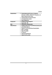
...y CPU shutdown when overheat y System Voltage Detect y Dual Marvell® 88E1116 GbE PHY y Supports WOL, PXE y Phoenix BIOS on 8Mb flash ROM y PS/2 Mouse wake up from S1 under Windows Operating System y External Modem wake up y Supports S1, S4, S5 under Windows Operating System y Wake on LAN (WOL) y Wake on Ring (WOR) y AC Recovery y Supports Console Redirection y Supports 4-pin Fan controller
5
Manual - Page 8
English
GA-3CESL3-RH Motherboard
Chapter 2 Hardware Installation Process
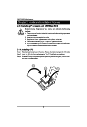
2-1: Installing Processor and CPU Haet Sink
Before installing the processor and cooling fan, adhere to the following cautions: 1. The processor will overheat without the heatsink and/or fan, resulting in permanent
irreparable damage. 2. Never force the processor into the socket. 3. Apply thermal grease on the processor ...
Manual - Page 9
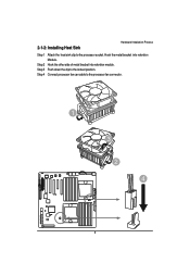
2-1-2: Installing Heat Sink
Hardware Installation Process
Step 1 Attach the heat sink clip to the processor socket. Hook the metal bracket into retention Module.
Step 2 Hook the other side of metal bracket into retention module. Step 3 Push down the clip to the locked position. Step 4 Connect processor fan can cable to the processor fan connector.
1
3 2 4
9
Manual - Page 10
English
GA-3CESL3-RH Motherboard
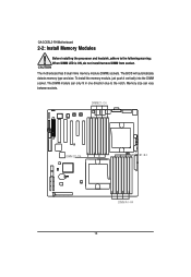
2-2: Install Memory Modules
Before installing the processor and heatsink, adhere to the following warning: When DIMM LED is ON, do not install/remove DIMM from socket.
The motherboard has 8 dual inline memory module (DIMM) sockets. The BIOS will automatically detects memory type and size. To install the memory module, just push it vertically into the DIMM socket ....
Manual - Page 11
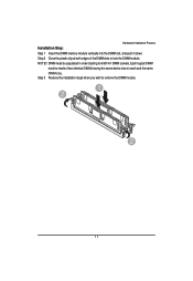
Hardware Installation Process
Installation Step: Step 1 Insert the DIMM memory module vertically into the DIMM slot, and push it down. Step 2 Close the plastic clip at both ... from B1/A1 DIMM sockets. Each logical DIMM
must be made of two identical DIMMs having the same device size on each and the same DIMM size. Step 3 Reverse the installation steps when you wish to remove the DIMM module.
1 2
2
11
Manual - Page 13
Hardware Installation Process
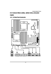
2-3: Connect ribbon cables, cabinet wires, and power supply
2-3-1 : I/O Back Panel Introduction
13
Manual - Page 14
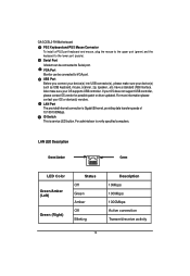
... USB controller. If your OS does not support USB controller, please contact OS vendor for possible patch or driver updated. For more information please contact your OS or device(s) vendors. LAN Port The provided Internet connection is Gigabit Ethernet, providing data transfer speeds of 10/100/1000Mbps. ID Switch This is service LED buttun. For administraor to verify specified computers.
LAN...
Manual - Page 22

English
GA-3CESL3-RH Motherboard 17) PS1 (SMBUS connector for power supply)
1
Pin No. Definition
1
SMBus Clock
2
SMBUS Data
3
SMBUS Alert
4
GND
5
3.3V
18/19 ) CPU1_FAN/CPU2_FAN (CPU0/1 fan cable connectors) Please note, a proper installation of the CPU cooler is essential to prevent the CPU from running under abnormal condition or damaged by overheating.The CPU fan connector supports...
Manual - Page 23
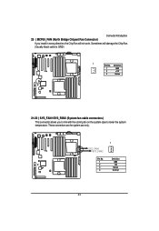
Connector Introduction 20 ) MCP55_FAN (North Bridge Chipset Fan Connector)
If you install in wrong direction, the Chip Fan will not work. Sometimes will damage the Chip Fan. (Usually black cable is GND)
1 Pin No. Definition
1
GND
2
+12V
3
Sense
21/22 ) SYS_FAN1/SYS_FAN2 (System fan cable connectors) This connector allows you to link with the cooling...
Manual - Page 24
English
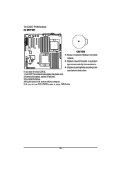
GA-3CESL3-RH Motherboard 23) BATTERY
CAUTION
Danger of explosion if battery is incorrectly
replaced.
Replace only with the same or equivalent
type recommended by the manufacturer.
Dispose of used batteries according to the
If you want to erase CMOS...
manufacturer's instructions.
1.Turn OFF the computer and unplug the power cord.
2.Remove the battery, wait for 30...
Manual - Page 28
GA-3CESL3-RH Motherboard
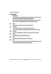
GETTINGHELP Main Menu The on-line description of the highlighted setup function is displayed at the bottom of the screen. Status Page Setup Menu / Option Page Setup Menu Press F1 to pop up a small help window that describes the appropriate keys to use and the possible selections for the highlighted item. To exit the Help Window press...
Manual - Page 36
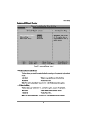
Advanced Chipset Control
BIOS Setup
Figure 2-3: Advanced Chipset Control
Wake on Keyboard/Mouse
This item allows you to set the enable/disable for powering-on the system by keyboard and
mouse.
Enabled
Wake on Keyboard/Mouse. (Default setting)
Disabled
Disable this function.
Note: This item must enabled if you're running under Windows operating system.
Wake On Ring
This item allow...
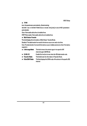
Manual - Page 41
GA-3CESL3-RH Motherboard
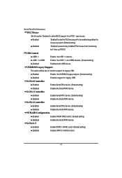
PS/2 Mouse
Set this option 'Enabled' to allow BIOS support for a PS/2 - type mouse.
Enabled
'Enabled' forces the PS/2 mouse port to be enabled regardless if a mouse is present. (Default setting)
Disabled
'Disabled' prevents any installed PS/2 mouse from functioning, but frees up IRQ12.
USB Control
USB1.1
Enable the USB 1.1 device.
USB1.1+USB2
Enable the USB 1.1 ...
Manual - Page 42
GA-3CESL3-RH Motherboard
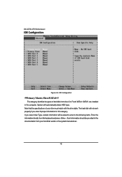
IDE Configuration
Figure 2-6: IDE Configuration
Primary Master, Slave/SATA0~5 The category identifies the types of hard disk from drive C to F and SATA 0~SATA 5 are installed in the computer. System will automatically detect HDD type. Note that the specifications of your drive must match with the drive table. The hard disk will not work properly if you enter improper ...
Manual - Page 43
BIOS Setup
TYPE
Auto: Set parameters automatically. (Default setting)
CD/DVD: Use fo CD/DVD ROM drives or double click [Auto] to set all HDD parameters
automatically.
Clear: Removable disk drive is installed here.
ATAPI Removable: Removable disk drive is installed here.
Multi-Sector Transfer
This field displays the information of Multi-Sector Transfer Mode.
Disabled: The data transfer ...
Manual - Page 44
GA-3CESL3-RH Motherboard
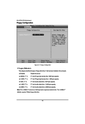
Floppy Configuration
Figure 2-7: Floppy Configuration
Legacy Diskette A
This category identifies the type of floppy disk drive A that has been installed in the computer.
Disabled
Disable this device.
360KB, 51/4 in. 31/2 inch AT-type high-density drive; 360K byte capacity
1.2MB, 31/2 in. 31/2 inch AT-type high-density drive; 1.2M byte capacity
720K, 31/2 in. 31/2 ...
Manual - Page 52
GA-3CESL3-RH Motherboard
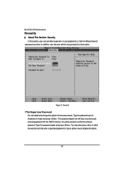
Security
* About This Section: Security In this section, user can set either supervisor or user passwords, or both for different level of
password securities. In addition, user also can set the virus protection for boot sector.
Figure 3: Security
Set Supervisor Password You can install and change this options for the setup menus. Type the password up to 6 characters in ...