Gigabyte GA-6LISL driver and firmware

Related Gigabyte GA-6LISL Manual Pages
Download the free PDF manual for Gigabyte GA-6LISL and other Gigabyte manuals at ManualOwl.com
Manual - Page 3
... Configuration 36 2-2-2 Trusted Computing (Optional 37 2-2-3 PCI Subsystem Settings 38 2-2-3-1 PCI Express Settings 40 2-2-4 CPU Configuration 42 2-2-5 SATA Configuration 47 2-2-5-1 Software Feature Mask Configuration 49 2-2-6 Info Report Configuration 51 2-2-7 USB Configuration 52 2-2-8 Super IO Configuration 53 2-2-9 Serial Port Console Redirection 55 2-2-10 Network Stack...58 2-2-11...
Manual - Page 5
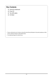
Box Contents
GA-6LISL motherboard Driver CD Two SATA cables I/O Shield
• The box contents above are for reference only and the actual items shall depend on the product package you obtain. The box contents are subject to change without notice.
• The motherboard image is for reference only.
- 5 -
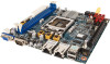
Manual - Page 7
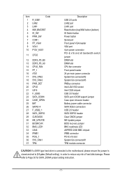
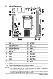
... USB 3.0 header SATA port 4 DOM support jumper Case open intrusion header Battery power cable connector SATA 6Gb/s connectors USB 2.0 header SATA SGPIO header Clear CMOS jumper ME Update jumper BIOS recovery jumper BMC readiness LED ASPEED 2300 BMC chipset IPMB connector PCI-E x16 slot System fan connector#1 TPM module connector
CAUTION! If a SATA type hard drive is connected to the motherboard...
Manual - Page 9
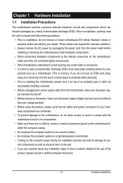
... a motherboard, CPU or memory. If you do not have an ESD wrist strap, keep your hands dry and first touch a metal object to eliminate static electricity. • Prior to installing the motherboard, please have it on top of an antistatic pad or within an electrostatic shielding container. • Before unplugging the power supply cable from the motherboard, make...
Manual - Page 10
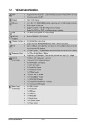
...® 2300 chipset
5 x SATA 6Gb/s connectors Support for Intel IRSTe SATA RAID 0, RAID 1, RAID 10, RAID 5 Up to 4 USB 2.0 ports (2 on the back panel, 2 via the USB brackets connected to the internal USB headers) 2 x USB 3.0 ports ( 2 via the USB brackets connected to the internal USB headers) 1 x PCIe x16 slot (Gen3 x16 bus) Supports 2 x PCIe x8 slots (Gen3 x8 bus) via riser card and CFG5 jumper...
Manual - Page 11
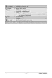
... temperature detection ŠŠ CPU/System fan speed detection ŠŠ CPU/System fan speed control * Whether the CPU/system fan speed control function is supported will depend on
the CPU/system cooler you install.
ŠŠ 1 x 128 Mbit flash ŠŠ AMI BIOS
Form Factor ŠŠ Mini ITX Form Factor; 6.7 inch x 6.7 inch
GIGABYTE reserves the right to make any...
Manual - Page 12
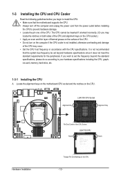
... not recommended
that the system bus frequency be set beyond hardware specifications since it does not meet the standard requirements for the peripherals. If you wish to set the frequency beyond the standard specifications, please do so according to your hardware specifications including the CPU, graphics card, memory, hard drive, etc.
1-3-1 Installing the CPU
A. Locate the alignment keys on...
Manual - Page 13
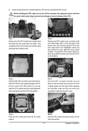
B. Follow the steps below to correctly install the CPU into the motherboard CPU socket.
Before installing the CPU, make sure to turn off the computer and unplug the power cord from the power outlet power plug to prevent any damage to prevent damage to the CPU.
Step 1: Gently press the CPU socket lever handle down and away from the socket with your finger...
Manual - Page 14
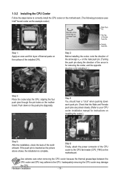
... closely. (Refer to your CPU cooler installation manual for instructions on installing the cooler.)
Step 5:
After the installation, check the back of the motherboard. If the push pin is inserted as the picture above shows, the installation is complete.
Step 6:
Finally, attach the power connector of the CPU cooler to the CPU fan header (CPU_FAN) on the motherboard.
Use extreme care when...
Manual - Page 15
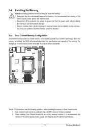
... you begin to install the memory: • Make sure that the motherboard supports the memory. It is recommended that memory of the
same capacity, brand, speed, and chips be used. • Always turn off the computer and unplug the power cord from the power outlet before installing
the memory to prevent hardware damage. • Memory modules have a foolproof design. A memory module can be...
Manual - Page 16
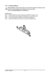
1-4-2 Installing a Memory
Before installing a memory module, make sure to turn off the computer and unplug the power cord from the power outlet to prevent damage to the memory module. Be sure to install DDR3 DIMMs on this motherboard. Installation Step: Step 1. Insert the DIMM memory module vertically into the DIMM slot, and push it down. Step 2. Close the plastic clip at both edges...
Manual - Page 17
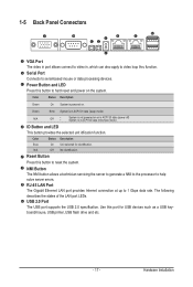
...a NMI to the processor to help solve server errors. RJ-45 LAN Port The Gigabit Ethernet LAN port provides Internet connection at up to 1 Gbps data rate. The following describes the states of the LAN port LEDs. USB 2.0 Port The USB port supports the USB 2.0 specification. Use this port for USB devices such as a USB keyboard/mouse, USB printer, USB flash drive and etc.
- 17 -
Hardware Installation
Manual - Page 18
...
Link between system and network or no
access
Blinking Data transmission or receiving is occurring
Off
No data transmission or receiving is occurring
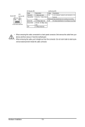
• When removing the cable connected to a back panel connector, first remove the cable from your device and then remove it from the motherboard.
• When removing the cable, pull it straight out...
Manual - Page 19
...14
76
1) ATX1 2) P12V_AUX1 3) CPU0_FAN (CPU Fan) 4) SYS_FAN1 (System Fan) 5) ...installing the devices, be sure to turn off the devices and your computer. Unplug the power
cord from the power outlet to prevent damage to the devices. • After installing the device and before turning on the computer, make sure the device cable has
been securely attached to the connector on the motherboard...
Manual - Page 20
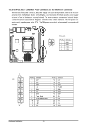
...the motherboard. Before connecting the power connector, first make sure the power supply
is turned off and all devices are properly installed. The power connector possesses a foolproof design.
Connect the power supply cable to the power connector in the correct orientation. The 12V power con-
ATA
nector mainly supplies power to the CPU. If the 12V power connector is not connected, the computer...
Manual - Page 27
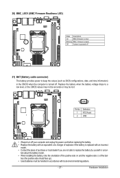
...firmware is initial
Blinking BMC firmware is ready
Off
System is powered off
21) BAT (Battery cable connector)
The battery provides power to keep the values (such as BIOS configurations, date, and time information) in the CMOS when the computer...by yourself or uncer-
tain about the battery model. • When installing the battery, note the orientation of the positive side (+) and the negative...
Manual - Page 34
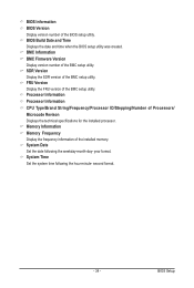
...BMC setup utility. FRU Version Display the FRU version of the BMC setup utility. Processor Information Processor Information CPU Type/Brand String/Frequency/Processor ID/Stepping/Number of Processors/ Microcode Revison Displays the technical specifications for the installed processor. Memory Information Memory Frequency Display the frequency information of the installed memory. System Date Set the...
Manual - Page 43
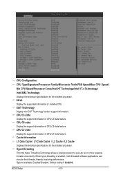
... technical specifications for the installed processor. Hyper-threading The Intel Hyper Threading Technology allows a single processor to execute two or more separate threads concurrently. When hyper-threading is enabled, multi-threaded software applications can execute their threads, thereby improving performance. Options available: Enabled/Disabled. Default setting is Enabled.
BIOS Setup
- 43 -
Manual - Page 48
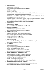
.... Default setting is Enabled. SATA Controller Speed
Indicates the maximum speed that the SATA controller can support. Options available: Default/Gen1/Gen2/Gen3. Default setting is Default. Software Feature Mask Configuration
Press [Enter] for configuration of advanced items. Serial Port 0/1/2/3/4/5
The category identifies Serial ATA type of hard disk that are installed in the computer. System...
Manual - Page 75
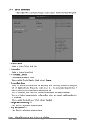
... menu
The Secure Boot Menu is applicable when your device is installed the Windows® 8 operatin system.
Platform Mode
Display the System Platform Mode State.
Secure Boot Display the status of Secure Boot. Secure Boot Control Enable/Disable Secure Boot function. Options available: Enabled/Disabled. Default setting is Disabled.
Secure Boot Mode Secure Boot requires all the...