Gigabyte GA-6LXSV driver and firmware

Related Gigabyte GA-6LXSV Manual Pages
Download the free PDF manual for Gigabyte GA-6LXSV and other Gigabyte manuals at ManualOwl.com
Manual - Page 3
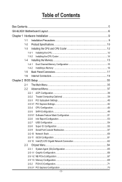
... Configuration 38 2-2-2 Trusted Computing (Optional 39 2-2-3 PCI Subsystem Settings 40 2-2-3-1 PCI Express Settings 42 2-2-4 CPU Configuration 44 2-2-5 SATA Configuration 49 2-2-5-1 Software Feature Mask Configuration 51 2-2-6 Info Report Configuration 53 2-2-7 USB Configuration 54 2-2-8 Super IO Configuration 55 2-2-9 Serial Port Console Redirection 57 2-2-10 Network Stack...60 2-2-11...
Manual - Page 5
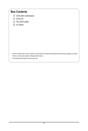
Box Contents
GA-6LXSV motherboard Driver CD Two SATA cables I/O Shield
• The box contents above are for reference only and the actual items shall depend on the product package you obtain. The box contents are subject to change without notice.
• The motherboard image is for reference only.
- 5 -
Manual - Page 9
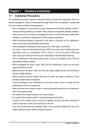
... a motherboard, CPU or memory. If you do not have an ESD wrist strap, keep your hands dry and first touch a metal object to eliminate static electricity. • Prior to installing the motherboard, please have it on top of an antistatic pad or within an electrostatic shielding container. • Before unplugging the power supply cable from the motherboard, make...
Manual - Page 10
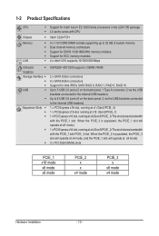
...® AST2300 supports 128MB VRAM
2 x SATA 3Gb/s connectors 4 x SATA 6Gb/s connectors Support for Intel IRSTe SATA RAID 0, RAID 1, RAID 5, RAID 10 Up to 5 USB 2.0 ports (2 on the back panel, 1 Type A connector, 2 via the USB brackets connected to the internal USB headers) Up to 6 USB 3.0 ports (4 on the back panel, 2 via the USB brackets connected to the internal USB headers) 1 x PCI Express x16...
Manual - Page 11
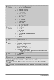
...;Š 1 x 128 Mbit flash ŠŠ AMI BIOS
Form Factor ŠŠ ATX Form Factor; 12 inch x 9.6 inch
* The Etron Stor Turbo software to improve storage device performance. Please refer to driver CD for installing the software.
* If you want to active the rear I/O USB 3.0 ports in Linux RedHat operating system, please update the kernel to the version 2.6.37.
GIGABYTE reserves the right...
Manual - Page 12
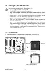
... guidelines before you begin to install the CPU: • Make sure that the motherboard supports the CPU.
(Go to GIGABYTE's website for the latest CPU support list.) • Always turn off the computer and unplug the power cord from the power outlet before installing
the CPU to prevent hardware damage. • Locate the pin one of the CPU. The CPU cannot be inserted if oriented...
Manual - Page 13
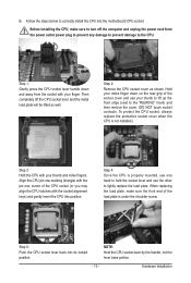
B. Follow the steps below to correctly install the CPU into the motherboard CPU socket.
Before installing the CPU, make sure to turn off the computer and unplug the power cord from the power outlet power plug to prevent any damage to prevent damage to the CPU.
Step 1: Gently press the CPU socket lever handle down and away from the socket with your finger...
Manual - Page 14
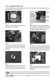
... closely. (Refer to your CPU cooler installation manual for instructions on installing the cooler.)
Step 5:
After the installation, check the back of the motherboard. If the push pin is inserted as the picture above shows, the installation is complete.
Step 6:
Finally, attach the power connector of the CPU cooler to the CPU fan header (CPU_FAN) on the motherboard.
Use extreme care when...
Manual - Page 15
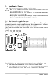
... you begin to install the memory: • Make sure that the motherboard supports the memory. It is recommended that memory of the
same capacity, brand, speed, and chips be used. • Always turn off the computer and unplug the power cord from the power outlet before installing
the memory to prevent hardware damage. • Memory modules have a foolproof design. A memory module can be...
Manual - Page 16
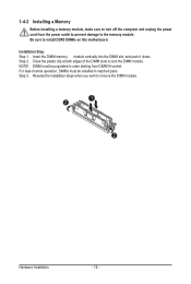
1-4-2 Installing a Memory
Before installing a memory module, make sure to turn off the computer and unplug the power cord from the power outlet to prevent damage to the memory module. Be sure to install DDR3 DIMMs on this motherboard.
Installation Step: Step 1. Insert the DIMM memory module vertically into the DIMM slot, and push it down. Step 2. Close the plastic clip at both edges...
Manual - Page 17
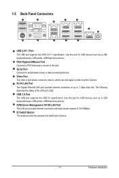
... for USB devices such as a USB keyboard/mouse, USB printer, USB flash drive and etc. PS/2 Keyboard/Mouse Port Coonnect a PS/2 keyboard or mouse to this port. Serial Port Connects to serial-based mouse or data processing devices. Video Port The video in port allows connect to video in, which can also apply to video loop thru function. RJ-45 LAN Port The Gigabit Ethernet LAN port provides Internet...
Manual - Page 18
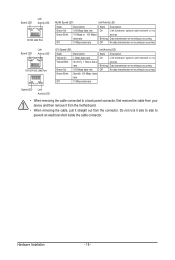
...LAN Port
MLAN Speed LED:
Link/Activity LED:
State Green On Green Blink
Off
Description 100 Mbps data rate 10 Mbps or 100 Mbps data rate 10 Mbps data rate
State Description
On
Link between system and network... system and network or no
...cable connected to a back panel connector, first remove the cable from your device and then remove it from the motherboard.
• When removing the cable...
Manual - Page 19
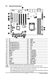
...SGPIO
2) P2
18) IPMB1
3) CPU0_FAN1 (CPU Fan)
19) BMC_LED2
4) SYS_FAN1 (System ...installing the devices, be sure to turn off the devices and your computer. Unplug the
power cord from the power outlet to prevent damage to the devices.
• After installing the device and before turning on the computer, make sure the device cable has
been securely attached to the connector on the motherboard...
Manual - Page 20
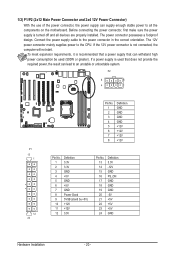
... on the motherboard. Before connecting the power connector, first make sure the power supply is turned off and all devices are properly installed. The power connector possesses a foolproof design. Connect the power supply cable to the power connector in the correct orientation. The 12V power connector mainly supplies power to the CPU. If the 12V power connector is not connected, the computer will...
Manual - Page 27
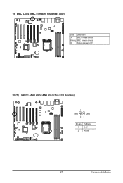
19) BMC_LED2 (BMC Firmware Readiness LED)
State Description
On
BMC firmware is initial
Blinking BMC firmware is ready
Off
System is powered off
20/21) LAN3/LAN4(LAN3/LAN4 link/active LED Headers)
11
LAN4
LAN3
22
Pin No. 1 2
Definition 3.3V Active
- 27 -
Hardware Installation
Manual - Page 36
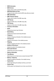
... processor. Microcode Revision Display Microcode revision information.
Memory Information Total Memory Determines how much total memory is present during the POST. Memory Frequency Display the frequency information of the installed memory. System Date Set the date following the weekday-month-day- year format. System Time Set the system time following the hour-minute- second format.
BIOS Setup...
Manual - Page 45
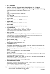
...enable the Intel Virtualization Technology function. VT allows a single platform to run multiple operating systems in independent partitions. Options available: Enabled/Disabled. Default setting is Enabled.
(Note)
This item is present only if you install a CPU that supports this feature. For more information about
Intel CPUs' unique features, please visit Intel's website.
- 45 -
BIOS Setup
Manual - Page 47
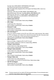
.../C3/C6/C7/C7s/C8/C9/C10/Auto. Default setting is Auto. Intel TXT (LT) Support
Enable/Disable Intel TXT (LT) support. Options available: Enabled/Disabled. Default setting is Disabled.
(Note)
This item is present only if you install a CPU that supports this feature. For more information about
Intel CPUs' unique features, please visit Intel's website.
- 47 -
BIOS Setup
Manual - Page 50
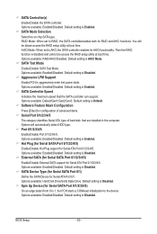
.... Default setting is Enabled. SATA Controller Speed
Indicates the maximum speed that the SATA controller can support. Options available: Default/Gen1/Gen2/Gen3. Default setting is Default. Software Feature Mask Configuration
Press [Enter] for configuration of advanced items. Serial Port 0/1/2/3/4/5
The category identifies Serial ATA type of hard disk that are installed in the computer. System...
Manual - Page 77
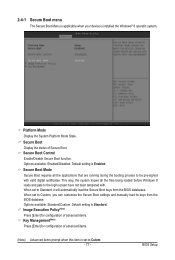
... menu
The Secure Boot Menu is applicable when your device is installed the Windows® 8 operatin system.
Platform Mode
Display the System Platform Mode State.
Secure Boot Display the status of Secure Boot. Secure Boot Control Enable/Disable Secure Boot function. Options available: Enabled/Disabled. Default setting is Enabled.
Secure Boot Mode Secure Boot requires all the...