Gigabyte GA-6PXSV2 driver and firmware

Related Gigabyte GA-6PXSV2 Manual Pages
Download the free PDF manual for Gigabyte GA-6PXSV2 and other Gigabyte manuals at ManualOwl.com
Manual - Page 2
... of this manual may be reproduced, copied, translated, transmitted, or published in any form or by any means without GIGABYTE's prior written permission.
Documentation Classifications In order to assist in the use of this product, GIGABYTE provides the following types of documentations:
For quick set-up of the product, read the Quick Installation Guide included with...
Manual - Page 3
... 14 1-4-2 Installing a Memory 15 1-4-3 DIMM Population Table 15 1-5 Back Panel Connectors 16 1-6 Internal Connectors 18
Chapter 2 BIOS Setup 33 2-1 The Main Menu 35 2-2 Advanced Menu 37
2-2-1 PCI Configuration...38 2-2-2 Trusted Computing 39 2-2-3 CPU Configuration 40 2-2-4 Runtime Error Logging 44 2-2-5 SATA Configuration 45 2-2-6 Super IO Configuration 46 2-2-7 Serial Port Console...
Manual - Page 5
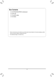
Box Contents
GA-6PXSV2/GA-6PXSV3 motherboard Driver CD Two SATA cables I/O Shield
• The box contents above are for reference only and the actual items shall depend on the product package you obtain. The box contents are subject to change without notice.
• The motherboard image is for reference only.
- 5 -
Manual - Page 8
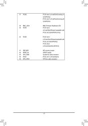
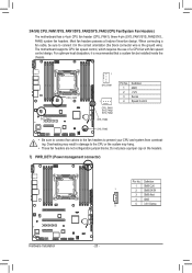
... x1/ GA-6PXSV2) PCI-E slot 4 (x4 slot/Gen2/running x2/ GA-6PXSV3)
BMC Firmware Readiness LED PCI-E slot 3 (x8 slot/Gen3/Shared bandwidth with PCI-E slot 2/GA-6PXSV2 Only)
PCI-E slot 2 (x16 slot/Gen3/Shared bandwidth with PCI-E slot 3/GA-6PXSV2) PCI-E slot 2 (x16 slot/Gen3/GA-6PXSV3)
ME recovery jumper S/PDIF header System fan cable connector PCI-E slot 1 (x16 slot/Gen3) CPU fan cable connector...
Manual - Page 9
... a motherboard, CPU or memory. If you do not have an ESD wrist strap, keep your hands dry and first touch a metal object to eliminate static electricity. • Prior to installing the motherboard, please have it on top of an antistatic pad or within an electrostatic shielding container. • Before unplugging the power supply cable from the motherboard, make...
Manual - Page 10
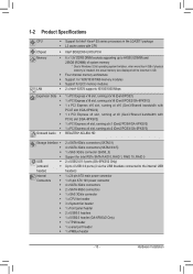
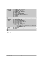
... SATA RAID 0, RAID 1, RAID 10, RAID 5 2 x USB 2.0/1.1 ports (GA-6PXSV2 Only) Up to 4 USB 3.0 ports (4 via the USB brackets connected to the internal USB headers)
1 x 24-pin ATX main power connector 1 x 8-pin ATX 12V power connector 4 x SATA 3Gb/s connectors 2 x SATA 6Gb/s connectors 1 x SAS 3Gb/s connector 1 x CPU fan header 3 x System fan header 1 x front panel header 2 x USB3.0 headers 1 x USB2...
Manual - Page 11
... Connectors
I/O Controller Hardware Monitor
BIOS Form Factor
ŠŠ 6 x USB 2.0/1.1 ports (GA-6PXSV3) ŠŠ 4 x USB 3.0 ports (GA-6PXSV2) ŠŠ 2 x USB 2.0/1.1 ports (GA-6PXSV2) ŠŠ 2 x RJ-45 LAN ports ŠŠ 1 x 10/100 Management LAN port ŠŠ 6 x Audio ports (4 x Line-out/1 x Line-in/1 x MIC) ŠŠ 1 x COM port ŠŠ 1 x VGA port
Š...
Manual - Page 12
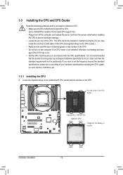
... guidelines before you begin to install the CPU: • Make sure that the motherboard supports the CPU.
(Go to GIGABYTE's website for the latest CPU support list.) • Always turn off the computer and unplug the power cord from the power outlet before installing
the CPU to prevent hardware damage. • Locate the pin one of the CPU. The CPU cannot be inserted if oriented...
Manual - Page 13
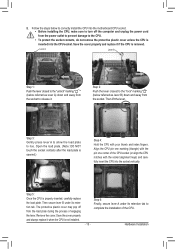
... steps below to correctly install the CPU into the motherboard CPU socket. •• Before installing the CPU, make sure to turn off the computer and unplug the power cord from the power outlet to prevent damage to the CPU.
•• To protect the socket contacts, do not remove the protective plastic cover unless the CPU is inserted into the...
Manual - Page 14
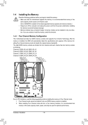
... you begin to install the memory: • Make sure that the motherboard supports the memory. It is recommended that memory of the
same capacity, brand, speed, and chips be used. (Go to GIGABYTE's website for the latest supported memory speeds and memory modules.) • Always turn off the computer and unplug the power cord from the power outlet before installing the memory to prevent hardware...
Manual - Page 15
1-4-2 Installing a Memory
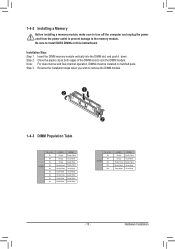
Before installing a memory module, make sure to turn off the computer and unplug the power cord from the power outlet to prevent damage to the memory module. Be sure to install DDR3 DIMMs on this motherboard.
Installation Step: Step 1. Insert the DIMM memory module vertically into the DIMM slot, and push it down. Step 2. Close the plastic clip at both edges...
Manual - Page 16
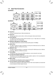
...Port The LAN port provides Internet connection with data transfer speeds of 10/100Mbps.
USB 3.0 Port The USB port supports the USB 3.0 specification. Use this port for USB devices such as a USB keyboard/mouse, USB printer, USB flash drive and etc. USB 2.0/1.1 Port The USB port supports the USB 2.0/1.1 specification. Use this port for USB devices such as a USB keyboard/mouse, USB printer, USB flash...
Manual - Page 17
...between system and network or no
... LED
10/100/1000 LAN Port
82574 Speed LED:
Link...cable connected to a back panel connector, first remove the cable from your device and then remove it from the motherboard.
• When removing the cable, pull it straight out from the connector. Do not rock it side to side to prevent an electrical short inside the cable connector.
- 17 -
Hardware Installation
Manual - Page 18
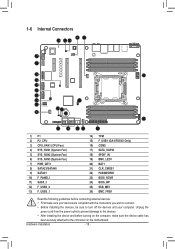
... connectors you wish to connect.
• Before installing the devices, be sure to turn off the devices and your computer. Unplug the
power cord from the power outlet to prevent damage to the devices.
• After installing the device and before turning on the computer, make sure the device cable has
been securely attached to the connector on the motherboard.
Hardware Installation
- 18 -
Manual - Page 19
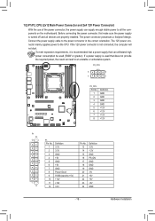
... on the motherboard. Before connecting the power connector, first make sure the power supply is turned off and all devices are properly installed. The power connector possesses a foolproof design. Connect the power supply cable to the power connector in the correct orientation. The 12V power connector mainly supplies power to the CPU. If the 12V power connector is not connected, the computer will...
Manual - Page 20
... design. When connecting a fan cable, be sure to connect it in the correct orientation (the black connector wire is the ground wire). The motherboard supports CPU fan speed control, which requires the use of a CPU fan with fan speed control design. For optimum heat dissipation, it is recommended that a system fan be installed inside the chassis.
CPU_FAN1 SYS_FAN1...
Manual - Page 28
...firmware is initial
Blinking BMC firmware is ready
Off
System is powered off
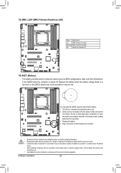
19) BAT1 (Battery)
The battery provides power to keep the values (such as BIOS configurations, date, and time information) in the CMOS when the computer... the battery by yourself or uncertain about the battery
model. • When installing the battery, note the orientation of the positive side (+) and the negative ...
Manual - Page 42
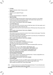
... installed CPU speed. 64-bit
Display the supported infprmation of installed CPU. Hyper-threading
The Intel Hyper Threading Technology allows a single processor to execute two or more separate threads concurrently. When hyper-threading is enabled, multi-threaded software applications can execute their threads, thereby improving performance. Options available: Enabled/Disabled. Default setting...
Manual - Page 5

Using the Web UI
The BMC firmware features an embedded web server, enabling users to connect to the BMC using an Internet browser (Microsoft® Internet Explorer™). The web server shall support 4 concurrent connections Web-based GUI is supported on the following browsers: Microsoft Windows: • Internet Explorer 6 and 7 • Mozilla® Firefox® 2.0 or later Linux...
Manual - Page 17

Updates
The firmware can be updated remotely. To update firmware, follow the instruction below: 1. Select Update Type. 2. Select the file on your local system using Browse. Click Upload to update to the new version of firmware.
16