Gigabyte GA-6PXSV4 driver and firmware

Related Gigabyte GA-6PXSV4 Manual Pages
Download the free PDF manual for Gigabyte GA-6PXSV4 and other Gigabyte manuals at ManualOwl.com
Manual - Page 2
... of this manual may be reproduced, copied, translated, transmitted, or published in any form or by any means without GIGABYTE's prior written permission.
Documentation Classifications In order to assist in the use of this product, GIGABYTE provides the following types of documentations:
For quick set-up of the product, read the Quick Installation Guide included with...
Manual - Page 3
...Internal Connectors 18
Chapter 2 BIOS Setup 33 2-1 The Main Menu 35 2-2 Advanced Menu 37
2-2-1 PCI Configuration...38 2-2-2 Trusted Computing 39 2-2-3 CPU Configuration 40 2-2-3-1 CPU Power Management Configuration 43 2-2-4 Runtime Error Logging 44 2-2-5 SATA Configuration 45 2-2-6 Super IO Configuration 47 2-2-7 Serial Port Console Redirection 49 2-3 Chipset Menu 53 2-3-1 North Bridge...
Manual - Page 5
Box Contents
GA-6PXSV4 motherboard Driver CD Two SATA cables I/O Shield
• The box contents above are for reference only and the actual items shall depend on the product package you obtain. The box contents are subject to change without notice.
• The motherboard image is for reference only.
- 5 -
Manual - Page 7
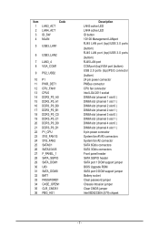
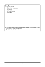
... 1 ) DIMM slot (channel 4 slot 0 ) DIMM slot (channel 4 slot 1 ) 8 pin power connector System fan #1/#3 connectors System fan #2 connector SATA 6Gb/s connectors SATA 3Gb/s connectors Front panel header SATA SGPIO header SATA port 1 DOM support jumper BIOS Upgrade ROM SATA port 0 DOM support jumper Battery socket Clear password jumper Chassis intrusion jumper Clear CMOS jumper Intel BD82C604 (X79...
Manual - Page 8
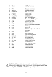
... plane board header SAS 3Gb/s connectors BIOS Recovery jumper USB 3.0 header USB 2.0 header SAS SGPIO header BIOS Write Protect jumper Force to Stop FRB3 Timer jumper TPM module connector Serial port cable header PCI 32bit/33MHz slot PCI-E x16 slot (Shared badwidth with PCIE3 slot) PCI-E x1 slot PCI-E x16 slot (Shared badwidth with PCIE1 slot) PCI-E slot BMC Upgrade ROM ASPEED AST2300 chipset BMC...
Manual - Page 9
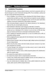
... a motherboard, CPU or memory. If you do not have an ESD wrist strap, keep your hands dry and first touch a metal object to eliminate static electricity. • Prior to installing the motherboard, please have it on top of an antistatic pad or within an electrostatic shielding container. • Before unplugging the power supply cable from the motherboard, make...
Manual - Page 10
...
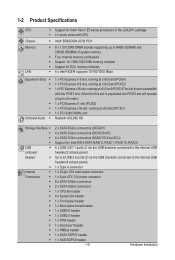
1 x 24-pin ATX main power connector
1 x 8-pin ATX 12V power connector
8 x SATA 3Gb/s connectors
2 x SATA 6Gb/s connectors
1 x CPU fan header
4 x System fan header
1 x Front panel header
1 x Back plane borad header
1 x USB3.0 header
1 x USB2.0 header
1 x TPM header
1 x Serial port header
1 x PMBus header
1 x SATA SGPIO header
1 x SAS SGPIO header
- 10 -
Hardware Installation
Manual - Page 11
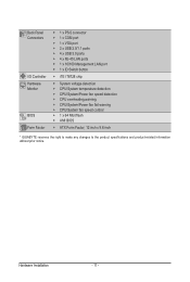
... ŠŠ CPU overheating warning ŠŠ CPU/System/Power fan fail warning ŠŠ CPU/System fan speed control ŠŠ 1 x 64 Mbit flash ŠŠ AMI BIOS
ŠŠ ATX Form Factor; 12 inch x 9.6 inch
* GIGABYTE reserves the right to make any changes to the product specifications and product-related information without prior notice.
Hardware Installation
- 11 -
Manual - Page 12
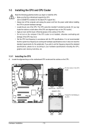
... guidelines before you begin to install the CPU: • Make sure that the motherboard supports the CPU.
(Go to GIGABYTE's website for the latest CPU support list.) • Always turn off the computer and unplug the power cord from the power outlet before installing
the CPU to prevent hardware damage. • Locate the pin one of the CPU. The CPU cannot be inserted if oriented...
Manual - Page 13
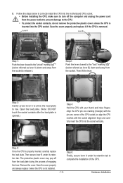
... steps below to correctly install the CPU into the motherboard CPU socket. •• Before installing the CPU, make sure to turn off the computer and unplug the power cord from the power outlet to prevent damage to the CPU.
•• To protect the socket contacts, do not remove the protective plastic cover unless the CPU is inserted into the...
Manual - Page 14
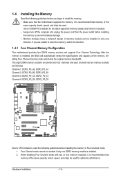
... you begin to install the memory: • Make sure that the motherboard supports the memory. It is recommended that memory of the
same capacity, brand, speed, and chips be used. (Go to GIGABYTE's website for the latest supported memory speeds and memory modules.) • Always turn off the computer and unplug the power cord from the power outlet before installing the memory to prevent hardware...
Manual - Page 15
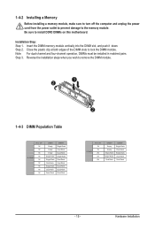
1-4-2 Installing a Memory
Before installing a memory module, make sure to turn off the computer and unplug the power cord from the power outlet to prevent damage to the memory module. Be sure to install DDR3 DIMMs on this motherboard.
Installation Step: Step 1. Insert the DIMM memory module vertically into the DIMM slot, and push it down. Step 2. Close the plastic clip at both edges...
Manual - Page 16
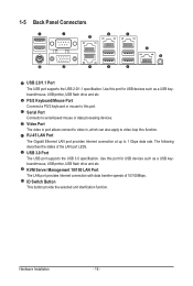
... for USB devices such as a USB keyboard/mouse, USB printer, USB flash drive and etc. PS/2 Keyboard/Mouse Port Coonnect a PS/2 keyboard or mouse to this port. Serial Port Connects to serial-based mouse or data processing devices. Video Port The video in port allows connect to video in, which can also apply to video loop thru function. RJ-45 LAN Port The Gigabit Ethernet LAN port provides Internet...
Manual - Page 17
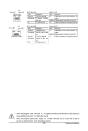
... Link between system and network or no
access
Blinking Data transmission or receiving is occurring
Off
No data transmission or receiving is occurring
• When removing the cable connected to a back panel connector, first remove the cable from your
device and then remove it from the motherboard.
• When removing the cable, pull it straight out...
Manual - Page 18
...
16
15 29
28 14
18 13
1
8 3
26 12
24 22 23 25
17 30 31
11
9
10 5
46
2
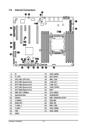
1) P1 2) P1_CPU 3) CPU_FAN1 (CPU Fan) 4) SYS_FAN1 (System Fan) 5) SYS_FAN2 (System Fan) 6) SYS_FAN3 (System Fan) 7) SYS_FAN4 (System Fan) 8) PWR_DET1 (PMBus) 9) SATA45/SATA23 10) SATA0/1... 25) PASSWORD1 26) BMC_FRB1BIOS_RCVR 27) SSB_ME1 28) BIOS_WP 29) BMC_FRB1 30) SATA_DOM0 31) SATA_DOM1
Hardware Installation
- 18 -
Manual - Page 19
... the connectors you wish to connect. • Before installing the devices, be sure to turn off the devices and your computer. Unplug the power
cord from the power outlet to prevent damage to the devices. • After installing the device and before turning on the computer, make sure the device cable has
been securely attached to the connector on the motherboard.
Hardware Installation
- 19 -
Manual - Page 20
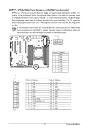
... on the motherboard. Before connecting the power connector, first make sure the power supply is turned off and all devices are properly installed. The power connector possesses a foolproof design. Connect the power supply cable to the power connector in the correct orientation. The 12V power connector mainly supplies power to the CPU. If the 12V power connector is not connected, the computer will...
Manual - Page 21
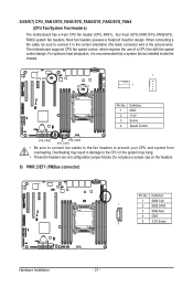
... ground wire). The motherboard supports CPU fan speed control, which requires the use of a CPU fan with fan speed control design. For optimum heat dissipation, it is recommended that a system fan be installed inside the chassis.
SYS_FAN4
CPU_FAN1
1 1
Pin No. 1 2 3 4
Definition GND +12V Sense Speed Control
SYS_FAN2
SYS_FAN3 SYS_FAN1
• Be sure to connect fan cables to the fan...
Manual - Page 22
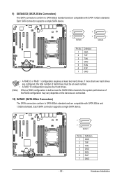
... four hard drives.
(Note) When a RAID configuration is built across the SATA 6Gb/s channels, the system performance of the RAID configuration may vary depends on the devices are connected.
10) SATA01 (SATA 6Gb/s Connectors) The SATA connectors conform to SATA 6Gb/s standard and are compatible with SATA 3Gb/s and 1.5Gb/s standard. Each SATA connector supports a single SATA device.
- 22...
Manual - Page 27
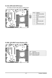
... header provides the SAS interface of SGPIO funtion.
Pin No. Definition
12
1 SGPIO_SAS_DATAIN
2 No Pin
3 SGPIO_SAS_DATAOUT
78
4 GND
5 GND
6 SGPIO_SAS_LOAD
7 NC
8 SGPIO_SAS_CLOCK
19) BMC_LED1 (BMC Firmware Readiness LED)
State Description
On
BMC firmware is initial
Blinking BMC firmware is ready
Off
System is powered off
- 27 -
Hardware Installation