Gigabyte GA-6UASV3 driver and firmware

Related Gigabyte GA-6UASV3 Manual Pages
Download the free PDF manual for Gigabyte GA-6UASV3 and other Gigabyte manuals at ManualOwl.com
Manual - Page 2
... of this manual may be reproduced, copied, translated, transmitted, or published in any form or by any means without GIGABYTE's prior written permission.
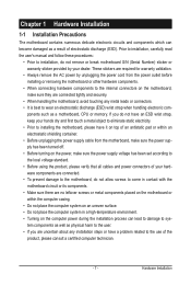
Documentation Classifications In order to assist in the use of this product, GIGABYTE provides the following types of documentations:
For quick set-up of the product, read the Quick Installation Guide included with...
Manual - Page 3
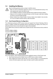
...Installing the Memory 13 1-4-1 Dual Channel Memory Configuration 13 1-4-2 Installing a Memory 14 1-5 Back Panel Connectors 15 1-6 Internal Connectors 16
Chapter 2 BIOS Setup 26 2-1 The Main Menu 28 2-2 Advanced Menu 30
2-2-1 Processor Configuration 31 2-2-2 Memory Configuration 34 2-2-3 Advanced Chipset Configuration 35 2-2-4 SATA Configuration 37 2-2-5 PCI Configuration...38 2-2-6 USB...
Manual - Page 4
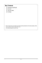
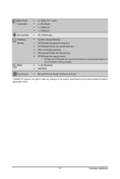
Box Contents
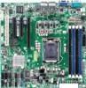
GA-6UASV3 motherboard Driver CD Two SATA cables I/O Shield
• The box contents above are for reference only and the actual items shall depend on the product package you obtain. The box contents are subject to change without notice.
• The motherboard image is for reference only.
- 4 -
Manual - Page 7
... a motherboard, CPU or memory. If you do not have an ESD wrist strap, keep your hands dry and first touch a metal object to eliminate static electricity. • Prior to installing the motherboard, please have it on top of an antistatic pad or within an electrostatic shielding container. • Before unplugging the power supply cable from the motherboard, make...
Manual - Page 8
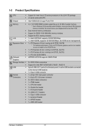
... install it in the PCIEX16 slot.
ŠŠ 1 x PCI Express x8 slot, running at x8 (PCIE_SLOT3)
ŠŠ 1 x PCI Express x8 slot, running at x4 (PCIE_SLOT2)
ŠŠ 1 x PCI slot 32-Bit/33MHz
Onboard
ŠŠ ASPEED AST2150 supports 32MB VRAM
Graphics
Storage Interface ŠŠ 6 x SATA 3Gb/s connectors
ŠŠ Support for Intel IRST SATA RAID 0, RAID 1, RAID 10
USB...
Manual - Page 9
... ŠŠ CPU overheating warning ŠŠ CPU/System/Power fan fail warning ŠŠ CPU/System fan speed control * Whether the CPU/system fan speed control function is supported will depend on
the CPU/system cooler you install. ŠŠ 1 x 64 Mbit flash ŠŠ AMI BIOS
Form Factor ŠŠ Micro ATX Form Factor; 9.6 inch x 9.6 inch
* GIGABYTE reserves the right...
Manual - Page 10
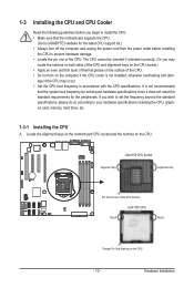
... guidelines before you begin to install the CPU: • Make sure that the motherboard supports the CPU.
(Go to GIGABYTE's website for the latest CPU support list.) • Always turn off the computer and unplug the power cord from the power outlet before installing
the CPU to prevent hardware damage. • Locate the pin one of the CPU. The CPU cannot be inserted if oriented...
Manual - Page 11
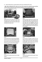
B. Follow the steps below to correctly install the CPU into the motherboard CPU socket.
Before installing the CPU, make sure to turn off the computer and unplug the power cord from the power outlet power plug to prevent any damage to prevent damage to the CPU.
Step 1: Gently press the CPU socket lever handle down and away from the socket with your finger...
Manual - Page 12
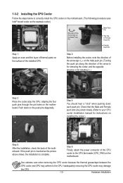
... closely. (Refer to your CPU cooler installation manual for instructions on installing the cooler.)
Step 5:
After the installation, check the back of the motherboard. If the push pin is inserted as the picture above shows, the installation is complete.
Step 6:
Finally, attach the power connector of the CPU cooler to the CPU fan header (CPU_FAN) on the motherboard.
Use extreme care when...
Manual - Page 13
... you begin to install the memory: • Make sure that the motherboard supports the memory. It is recommended that memory of the
same capacity, brand, speed, and chips be used. (Go to GIGABYTE's website for the latest supported memory speeds and memory modules.) • Always turn off the computer and unplug the power cord from the power outlet before installing the memory to prevent hardware...
Manual - Page 14
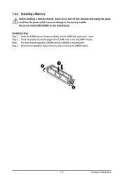
1-4-2 Installing a Memory
Before installing a memory module, make sure to turn off the computer and unplug the power cord from the power outlet to prevent damage to the memory module. Be sure to install DDR3 DIMMs on this motherboard. Installation Step: Step 1. Insert the DIMM memory module vertically into the DIMM slot, and push it down. Step 2. Close the plastic clip at both edges...
Manual - Page 15
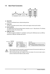
... apply to video loop thru function.
RJ-45 LAN Port The Gigabit Ethernet LAN port provides Internet connection at up to 1 Gbps data rate. The following describes the states of the LAN port LEDs.
USB 2.0/1.1 Port The USB port supports the USB 2.0/1.1 specification. Use this port for USB devices such as a USB keyboard/mouse, USB printer, USB flash drive and etc.
Connection/ Activity LED Speed LED...
Manual - Page 16
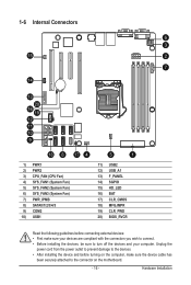
... the connectors you wish to connect. • Before installing the devices, be sure to turn off the devices and your computer. Unplug the
power cord from the power outlet to prevent damage to the devices. • After installing the device and before turning on the computer, make sure the device cable has
been securely attached to the connector on the motherboard.
- 16 -
Hardware...
Manual - Page 17
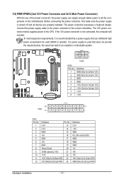
... on the motherboard. Before connecting the power connector, first make sure the power supply is turned off and all devices are properly installed. The power connector possesses a foolproof design. Connect the power supply cable to the power connector in the correct orientation. The 12V power connector mainly supplies power to the CPU. If the 12V power connector is not connected, the computer will...
Manual - Page 18
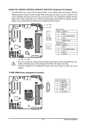
... design. When connecting a fan cable, be sure to connect it in the correct orientation (the black connector wire is the ground wire). The motherboard supports CPU fan speed control, which requires the use of a CPU fan with fan speed control design. For optimum heat dissipation, it is recommended that a system fan be installed inside the chassis.
SYS_FAN3 CPU_FAN...
Manual - Page 19
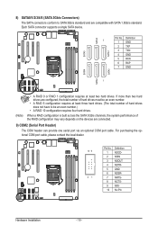
... 10 configuration requires four hard drives.
When a RAID configuration is built across the SATA 3Gb/s channels, the system performance of the RAID configuration may vary depends on the devices are connected.
9) COM2 (Serial Port Header) The COM header can provide one serial port via an optional COM port cable. For purchasing the optional COM port cable, please contact the local dealer.
Pin No...
Manual - Page 20
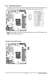
... USB bracket, please contact the local dealer.
Pin No. Definition
10 9
1 Power (5V)
2 Power (5V)
3 USB DX-
4 USB DY-
5 USB DX+
21
6 USB DY+
7 GND
8 GND
9 No Pin
10 NC
When the system is in S4/S5 mode, only the USB ports routed to the F_USB1 header can support the ON/OFF Charge function.
12) USB_A1 (Type A USB Headers)
- 20 -
Hardware Installation
Manual - Page 21
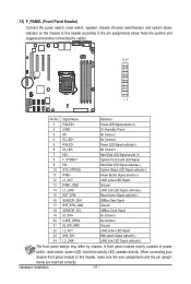
...cables.
12 24
12
Pin No. Signal Name
Definition
1 PWLED+
Power LED Signal anode (+)
2 5VSB
5V Stanndby Power
3 NC
No Connect
4 ID_LED+
No Connect
5 PWLED-
Power LED Signal cathode(-)
6 ID_LED-
No Connect
7 HD+
Hard Disk LED Signal anode (+)
8 F_SYSRDY
System Front board LED Signal
9 HD-
Hard Disk... power
switch, reset switch, power LED, hard drive ...
Manual - Page 22
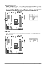
... Bus Adapter (HBA) and a backplane. Out of the 4 signals, 3 are driven by the HBA and 1 is driven by the backplane. Typically, the HBA is a storage controller located inside a server, desktop, rack or workstation computer that interfaces with Hard disk drives (HDDs) to store and retrieve data.
Pin No. Definition 4
1 Load
2 Clock
3 Data 0
1
4 NC
15) HD_LED Attach the connector cable from...
Manual - Page 23
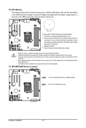
... • When installing the battery, note the orientation of the positive side (+) and the negative side (-) of the battery (the positive
side should face up). • Used batteries must be handled in accordance with local environmental regulations.
17) MFGJMPR (ME Recovery Jumper)
1 1-2 Close: Enable ME recovery. (Default setting)
1 2-3 Close: Disable ME recovery.
Hardware Installation
- 23 -