Gigabyte GA-7TCSV1 driver and firmware

Related Gigabyte GA-7TCSV1 Manual Pages
Download the free PDF manual for Gigabyte GA-7TCSV1 and other Gigabyte manuals at ManualOwl.com
Manual - Page 2
...
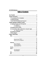
2.2.Installing memory modules 11 2.3.Connect ribbon cables, cabinet wires, and power supply 13
2.3.1. I/O Back Panel Introduction 13
2.4.Connectors Introduction 16 2.5.Block Diagram 24 Chapter 3 BIOS Setup 25 Main ...27
...27
Advanced Processor Options 29 Nehalem CPU Power Management 30 ...31
Advanced 35
Memory Configuration ...36 I/O Device Configuration 37 Advanced Chipset Control 39...
Manual - Page 3
English
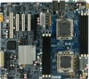
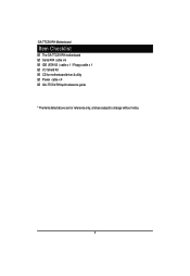
GA-7TCSV-RH Motherboard
Item Checklist
The GA-7TCSV-RH motherboard Serial ATA cable x 6 IDE (ATA100 ) cable x 1 / Floppy cable x 1 I/O Shield Kit CD for motherboard driver & utility Power cable x 4 GA-7TCSV-RH quick reference guide
* The items listed above are for reference only, and are subject to change without notice.
3
Manual - Page 4
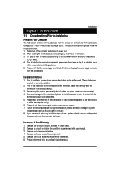
...: 1. Please turn off the computer and unplug its power cord. 2. When handling the motherboard, avoid touching any metal leads or connectors. 3. It is best to wear an electrostatic discharge (ESD) cuff when handling electronic components
(CPU, RAM). 4. Prior to installing the electronic components, please have these items on top of an antistatic pad or
within a electrostatic...
Manual - Page 5
English
GA-7TCSV-RH Motherboard
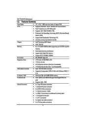
1.2. Features Summary
Form Factor CPU
Chipset Memory
I/O Control Expansion Slots
SATA RAID Controller On-Board VGA On-Board LAN Internal Connector
12" x 10.5" CEB size form factor, 8 layers PCB Supports Dual Intel® Xeon® Nehalem-EP 2S processors Xeon® Quad Core in LGA 1366 socket Supports 667/1066/1333MHz FSB &#...
Manual - Page 6
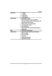
...; CPU shutdown when overheat System Voltage Detect Support basic ASF remote transaction through CSA Bus with hardware circuit Phoenix BIOS on 8Mb flash RAM Supports S3, S4, S5 under Windows Operating System Wake on LAN (WOL) Wake on Ring (WOR) AC Recovery Supports Console Redirection Supports 4-pin Fan controller
6
Manual - Page 9
... the socket. 3. Apply thermal grease on the processor before placing cooling fan. 4. Please make sure the CPU type is supported by the motherboard. 5. If you do not match the CPU socket Pin 1 and CPU cut edge well, it will cause
improper installation. Please change the insert orientation.
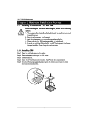
2.1.1. Installing CPU
Step 1 Raise the metal locking lever on the socket. Step...
Manual - Page 10
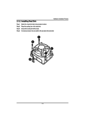
2.1.2. Installing Heat Sink
Hardware Installation Process
Step 1 Step 2 Step 3 Step 4
Attach the heat sink clip to the processor socket. Place the cooling fan on the heat sink. Secure the cooing fan with screws. Connect processor fan can cable to the processor fanconnector
1 1
1 1 2
10
Manual - Page 11
... sure that the computer
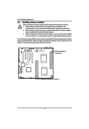
power is switched off to prevent hardware damage. 3. Memory modules have a foolproof insertion design. A memory module can be installed
in only one direction. If you are unable to insert the module, please switch the direction. The motherboard supports DDR3 memory modules, whereby BIOS will automatically detect memory capacity and specifications. Memory modules are designed...
Manual - Page 12
Hardware Installation Process
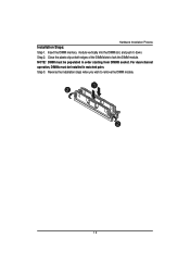
Installation Steps: Step 1. Insert the DIMM memory module vertically into the DIMM slot, and push it down. Step 2. Close the plastic clip at both edges of the DIMM slots to lock the ...
Manual - Page 14
....
LAN Port
The provided Internet connection is Gigabit Ethernet, providing data transfer speeds of 10/100/1000Mbps.
USB Port
Before you connect your device(s) into USB connector(s), please make sure your device(s) such as USB keyboard, mouse, scanner, zip, speaker...etc. have a standard USB interface. Also make sure your OS supports USB controller. If your OS does not support USB controller...
Manual - Page 17
... sure that all components and devices are properly installed. Align the power connector with its proper location on the motherboard and connect tightly. The ATX_12V power connector mainly supplies power to the CPU. If the ATX_12V power connector is not connected, the system will not start. Caution! Please use a power supply that is able to support the system voltage requirements...
Manual - Page 19
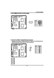
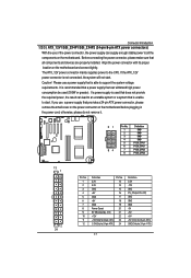
6 ) PS1 (SMBUS connector for power supply)
Connector Introduction
Pin No. Definition
1
1
SMBus Clock
2
SMBUS Data
3
SMBUS Alert
4
GND
5
3.3V
7/ 8/ 9/10/11/12 ) SATA 0~5 (Serial ATA cable connectors)
SATA 3Gb/s can provide up to 300MB/s stransfer rate. Please refer to the BIOS setting for the SATA 3Gb/s and install the proper driver in order to work properly.
7
Pin No. Definition
1...
Manual - Page 22
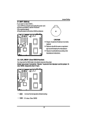
... for 30 second. 3.Re-install the battery. 4.Plug the power cord and turn ON the computer.
Jumper Setting
CAUTION Danger of explosion if battery is incorrectly
replaced. Replace only with the same or equivalent
type recommended by the manufacturer. Dispose of used batteries according to the
manufacturer's instructions.
22 ) CLR_CMOS1 (Clear CMOS...
Manual - Page 26
.... To exit the Help Window press . Select the Load Setup Defaults item in the BIOS Exit Setup menu when somehow the system is not stable as usual. This action makes the system reset to the default settings for stability.
z Main This setup page includes all the items in standard compatible BIOS.
z Advanced This setup page includes all the items...
Manual - Page 28
BIOS Setup
SATA Port 1/2/3/4/5/6
The category identifies the types of Serial SATA hard disk from drive 1 to 6 that has been installed in the computer. System will automatically detect HDD type. Note that the specifications of your drive must match with the drive table. The hard disk will not work properly if you enter improper information for this category. Hard drive information should be labled...
Manual - Page 38
... support for legacy USB (Default setting) Disabled Disables support for legacy USB. Route Port 80h cycles to Set route port 80h cycles to either PCI or LPC bus.
PCI LPC Serial ATA
Set Route Port 80h I/O cycles to the PCI bus. (Default setting) Set Route Port 80h I/O cycles to the LPC bus.
Enabled Disabled
Enables on-board serial ATA function. (Default setting) Disables on-board serial ATA...
Manual - Page 43
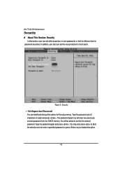
... for boot sector.
Figure 3: Security
Set Supervisor Password You can install and change this options for the setup menus. Type the password up to 6 characters in lengh and press . The password typed now will clear any previously entered password from the CMOS memory. You will be asked to confirm the entered password. Type the password again and press . You may...
Manual - Page 48
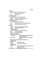
Flow Control This option provide user to enable the flow control function.
None
Not supported.
XON/OFF
Software control.
CTS/RTS
Hardware control. (Default setting)
BIOS Setup
Continue C.R. after POST
This option allows user to enable console redirection after O.S has loaded.
On
Enable console redirection after O.S has loaded.
Off
Disable this function. (Default setting)
48