Gigabyte GA-M68MT-D3 driver and firmware
Drivers and firmware downloads for this Gigabyte item

Related Gigabyte GA-M68MT-D3 Manual Pages
Download the free PDF manual for Gigabyte GA-M68MT-D3 and other Gigabyte manuals at ManualOwl.com
Manual - Page 3
...order to assist in the use of this product, GIGABYTE provides the following types of documentations:
For detailed product information, carefully read the User's Manual. For instructions on how to use GIGABYTE's unique features, read or download the information on/from the Support&Downloads\Motherboard\Technology Guide page on our website.
For product-related information, check...
Manual - Page 4
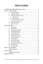
...-M68MT-D3/GA-M68MT-S2P Motherboard Layout 5 Chapter 1 Hardware Installation 6
1-1 Installation Precautions 6 1-2 Product Specifications 7 1-3 Installing the CPU and CPU Cooler 9
1-3-1 Installing the CPU...9 1-4 Installing the Memory 9
1-4-1 Dual Channel Memory Configuration 10 1-5 Installing an Expansion Card 10 1-6 Back Panel Connectors 10 1-7 Internal Connectors 12
Chapter 2 BIOS Setup...
Manual - Page 5
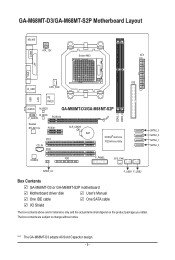
... DDR3_2
USB
iTE IT8720
AUDIO M_BIOS
GA-M68MT-D3/GA-M68MT-S2P
B_BIOS F_AUDIO
PCIEX16
Realtek RTL8211CL
PCIEX1
PCI1
CD_IN PCI2
CLR_CMOS BAT
NVIDIA® GeForce 7025/nForce 630a
CODEC
FDD
F_PANEL
SYS_FAN
SATA2_3 SATA2_2 SATA2_1 SATA2_0
SPDIF_IO
F_USB1 F_USB2
Box Contents
GA-M68MT-D3 or GA-M68MT-S2P motherboard
Motherboard driver disk
User's Manual
One IDE cable
One SATA cable...
Manual - Page 6
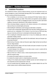
... a motherboard, CPU or memory. If you do not have an ESD wrist strap, keep your hands dry and first touch a metal object to eliminate static electricity. • Prior to installing the motherboard, please have it on top of an antistatic pad or within an electrostatic shielding container. • Before unplugging the power supply cable from the motherboard, make...
Manual - Page 7
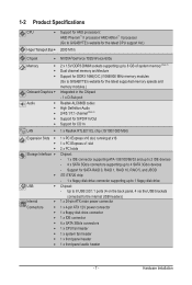
...; 2 x PCI slots
Storage Interface Chipset: - 1 x IDE connector supporting ATA-133/100/66/33 and up to 2 IDE devices - 4 x SATA 3Gb/s connectors supporting up to 4 SATA 3Gb/s devices - Support for SATA RAID 0, RAID 1, RAID 10, RAID 5, and JBOD iTE IT8720 chip:
- 1 x floppy disk drive connector supporting up to 1 floppy disk drive USB Chipset...
Manual - Page 8
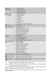
... installed, the actual memory size displayed will be less than 4 GB.
(Note 2) To configure 7.1-channel audio, you have to use an HD front panel audio module and enable the multi-channel audio feature through the audio driver.
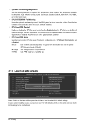
(Note 3) Whether the CPU fan speed control function is supported will depend on the CPU cooler you install. (Note 4) Available functions in EasyTune may differ by motherboard...
Manual - Page 9
...AM3 CPU
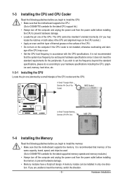
1-4 Installing the Memory
Read the following guidelines before you begin to install the memory: • Make sure that the motherboard supports the memory. It is recommended that memory of the
same capacity, brand, speed, and chips be used. (Go to GIGABYTE's website for the latest supported memory speeds and memory modules.) • Always turn off the computer and unplug the power cord...
Manual - Page 10

...begin to install an expansion card: • Make sure the motherboard supports the expansion card. Carefully read the manual that came
with your expansion card. • Always turn off the computer and unplug the power cord from the power outlet before installing
an expansion card to prevent hardware damage.
1-6 Back Panel Connectors
PS/2 Keyboard and PS/2 Mouse Port Use the upper port (green) to...
Manual - Page 11
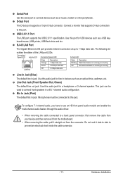
... other peripherals. D-Sub Port
The D-Sub port supports a 15-pin D-Sub connector. Connect a monitor that supports D-Sub connection
to this port.
USB 2.0/1.1 Port
The USB port supports the USB 2.0/1.1 specification. Use this port for USB devices such as a USB keyboard/mouse, USB printer, USB flash drive and etc. RJ-45 LAN Port
The Gigabit Ethernet LAN port provides Internet connection at up to...
Manual - Page 12
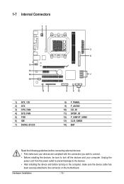
... the connectors you wish to connect. • Before installing the devices, be sure to turn off the devices and your computer. Unplug the
power cord from the power outlet to prevent damage to the devices. • After installing the device and before turning on the computer, make sure the device cable has
been securely attached to the connector on the motherboard.
Hardware Installation
- 12 -
Manual - Page 13
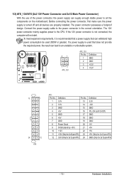
... on the motherboard. Before connecting the power connector, first make sure the power supply is turned off and all devices are properly installed. The power connector possesses a foolproof design. Connect the power supply cable to the power connector in the correct orientation. The 12V power connector mainly supplies power to the CPU. If the 12V power connector is not connected, the computer will...
Manual - Page 20
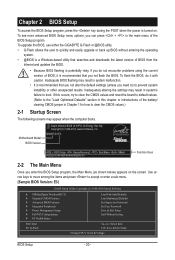
...; Advanced BIOS Features Integrated Peripherals Power Management Setup PnP/PCI Configurations PC Health Status
ESC: Quit F8: Q-Flash
Load Fail-Safe Defaults Load Optimized Defaults Set Supervisor Password Set User Password Save & Exit Setup Exit Without Saving
Select Item F10: Save & Exit Setup Change CPU's Clock & Voltage
BIOS Setup
- 20...
Manual - Page 23
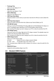
... Control
Allows you to set the memory voltage. Normal Supplies the memory voltage as required. (Default) -0.05V ~ +0.4V The adjustable range is from -0.05V to +0.4V.
Note: Increasing memory voltage may result in damage to the memory or reduce the useful life of the memory. Normal CPU Vcore
Displays the normal operating voltage of your CPU.
2-4 Standard CMOS Features
CMOS Setup...
Manual - Page 25
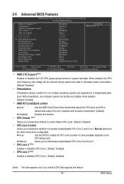
2-5 Advanced BIOS Features
CMOS Setup Utility-Copyright (C) 1984-2010 Award Software Advanced BIOS Features
AMD C1E Support (Note) Virtualization AMD K8 Cool&Quiet control CPU Unlock (Note) CPU core Control x CPU core 2 (Note) x CPU core 3 (Note) } Hard Disk Boot Priority First Boot Device Second Boot Device Third Boot Device Password Check HDD S.M.A.R.T. ...
Manual - Page 26
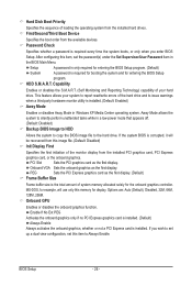
... system to copy the BIOS image file to the hard drive. If the system BIOS is corrupted, it will
be recovered from this image file. (Default: Disabled) Init Display First
Specifies the first initiation of the monitor display from the installed PCI graphics card, PCI Express
graphics card, or the onboard graphics.
PCI Slot
Sets the PCI graphics card as the first display.
Onboard VGA Sets the...
Manual - Page 29
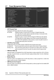
... the system to be awakened from an ACPI sleep state by a wake-up signal from a modem that supports wake-up function. (Default: Enabled) USB Resume from Suspend
Allows the system to be awakened from ACPI S3 sleep state by a wake-up signal from the installed USB device. (Default: Enabled)
(Note) Supported on Windows 7/Vista operating system only. - 29 -
BIOS Setup
Manual - Page 32
... 4-pin CPU fan.
2-10 Load Fail-Safe Defaults
CMOS Setup Utility-Copyright (C) 1984-2010 Award Software
MB Intelligent Tweaker(M.I.T.)
Load Fail-Safe Defaults
Standard CMOS Features
Load Optimized Defaults
Advanced BIOS Features
Set Supervisor Password
Integrated Peripherals
Set User Password
Power Management Setup PnP/PCI...
Manual - Page 33
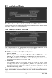
... updating the BIOS or after clearing the CMOS values.
2-12 Set Supervisor/User Password
CMOS Setup Utility-Copyright (C) 1984-2010 Award Software
MB Intelligent Tweaker(M.I.T.) Standard CMOS Features Advanced BIOS Features Integrated Peripherals Power Management Setup PnP/PCI Configurations Enter Password: PC Health Status
Load...
Manual - Page 35
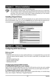
.../XP setup disk. • Motherboard driver disk.
Configuring the Onboard SATA Controller A. Installing SATA hard drive(s) in your computer
Attach one end of the SATA signal cable to the rear of the SATA hard drive and the other end to available SATA port on the motherboard. Then connect the power connector from your power supply to the hard drive. B. Configuring SATA controller mode in BIOS Setup...
Manual - Page 36
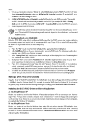
... SCSI or RAID driver." Insert the floppy disk containing the SATA controller driver. Follow the on-screen instructions to install the two drivers displayed. When completed, proceed with the Windows XP installation. B. Installing Windows Vista
Restart your system to boot from the Windows Vista setup disk and perform standard OS installation steps. Select Load Driver. Insert the floppy disk/USB...