Gigabyte MATMH81 driver and firmware

Related Gigabyte MATMH81 Manual Pages
Download the free PDF manual for Gigabyte MATMH81 and other Gigabyte manuals at ManualOwl.com
Manual - Page 3
... the CPU...12 1-3-2 Installing the CPU Cooler 14 1-4 Installing the Memory 15 1-4-1 Installing a Memory 15 1-5 Back Panel Connectors 16 1-6 Internal Connectors 17
Chapter 2 BIOS Setup 33 2-1 The Main Menu 35 2-2 Advanced Menu 37
2-2-1 ACPI Settings...38 2-2-2 S5 RTC Wake Settings 39 2-2-3 Trusted Computing (Optional 40 2-2-4 CPU Configuration 41 2-2-5 SATA Configuration 43 2-2-6 USB...
Manual - Page 4
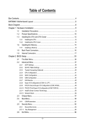
Box Contents
Motherboard Driver CD I/O Shield
• The box contents above are for reference only and the actual items shall depend on the product package you obtain. The box contents are subject to change without notice.
• The motherboard image is for reference only.
- 4 -
Manual - Page 9
... a motherboard, CPU or memory. If you do not have an ESD wrist strap, keep your hands dry and first touch a metal object to eliminate static electricity. • Prior to installing the motherboard, please have it on top of an antistatic pad or within an electrostatic shielding container. • Before unplugging the power supply cable from the motherboard, make...
Manual - Page 10
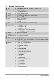
... ATX main power connector ŠŠ 2 x SATA 6Gb/s connectors ŠŠ 1 x CPU fan header ŠŠ 2 x System fan header ŠŠ 8 x Serial port cable connectors ŠŠ 2 x COM power select connectors ŠŠ 1 x Front panel header ŠŠ 1 x Audio header ŠŠ 3 x USB 2.0 headers ŠŠ 1 x LVDS connector ŠŠ 1 x Brightness control connector...
Manual - Page 11
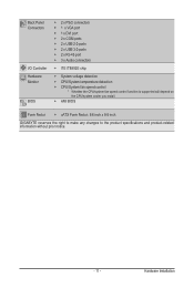
...138;Š 2 x USB 3.0 ports ŠŠ 2 x RJ-45 port ŠŠ 3 x Audio connectors
ŠŠ iTE IT8892E chip
ŠŠ System voltage detection ŠŠ CPU/System temperature detection ŠŠ CPU/System fan speed control * Whether the CPU/system fan speed control function is supported will depend on
the CPU/system cooler you install. ŠŠ AMI BIOS
Form Factor...
Manual - Page 12
... not recommended
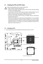
that the system bus frequency be set beyond hardware specifications since it does not meet the standard requirements for the peripherals. If you wish to set the frequency beyond the standard specifications, please do so according to your hardware specifications including the CPU, graphics card, memory, hard drive, etc.
1-3-1 Installing the CPU
A. Locate the alignment keys on...
Manual - Page 13
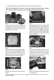
B. Follow the steps below to correctly install the CPU into the motherboard CPU socket.
Before installing the CPU, make sure to turn off the computer and unplug the power cord from the power outlet power plug to prevent any damage to prevent damage to the CPU.
Step 1: Gently press the CPU socket lever handle down and away from the socket with your finger...
Manual - Page 14
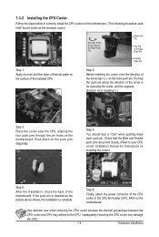
... closely. (Refer to your CPU cooler installation manual for instructions on installing the cooler.)
Step 5:
After the installation, check the back of the motherboard. If the push pin is inserted as the picture above shows, the installation is complete.
Step 6:
Finally, attach the power connector of the CPU cooler to the CPU fan header (CPU_FAN) on the motherboard.
Use extreme care when...
Manual - Page 15
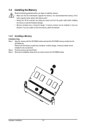
... you begin to install the memory: • Make sure that the motherboard supports the memory. It is recommended that memory of the
same capacity, brand, speed, and chips be used. • Always turn off the computer and unplug the power cord from the power outlet before installing
the memory to prevent hardware damage. • Memory modules have a foolproof design. A memory module can be...
Manual - Page 16
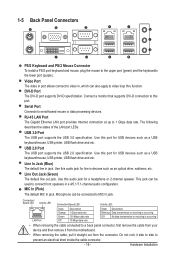
...port.
Serial Port Connects to serial-based mouse or data processing devices.
RJ-45 LAN Port The Gigabit Ethernet LAN port provides Internet connection at up to 1 Gbps data rate. The following describes the states of the LAN port LEDs.
USB 3.0 Port The USB port supports the USB 3.0 specification. Use this port for USB devices such as a USB keyboard/mouse, USB printer, USB flash drive and etc.
USB...
Manual - Page 17
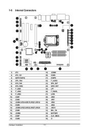
... 25) LPT 26) F_PANEL 27) LVDS 28) JRS6 29) JRS7 30) JRS8 31) JRS9 32) JRS10 33) BKL_CN 34) BATTERY 35) CLR_CMOS 36) CI
Hardware Installation
- 17 -
Manual - Page 18
... the connectors you wish to connect. • Before installing the devices, be sure to turn off the devices and your computer. Unplug the power
cord from the power outlet to prevent damage to the devices. • After installing the device and before turning on the computer, make sure the device cable has
been securely attached to the connector on the motherboard.
- 18 -
Hardware...
Manual - Page 19
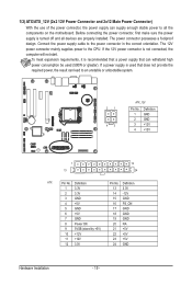
... the motherboard. Before connecting the power connector, first make sure the power
supply is turned off and all devices are properly installed. The power connector possesses a foolproof
design. Connect the power supply cable to the power connector in the correct orientation. The 12V
power connector mainly supplies power to the CPU. If the 12V power connector is not connected, the
computer will...
Manual - Page 20
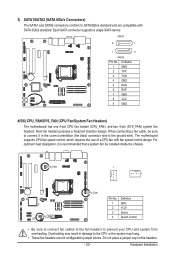
... the ground wire). The motherboard supports CPU fan speed control, which requires the use of a CPU fan with fan speed control design. For optimum heat dissipation, it is recommended that a system fan be installed inside the chassis.
SYS_FAN
1 1
SYS_FAN2
CPU_FAN
Pin No. 1 2 3 4
Definition GND +12V Sense Speed Control
• Be sure to connect fan cables to the fan headers...
Manual - Page 21
...
F
9 No Pin
9 No Pin
SPDIF_IO 9
No Pin
10 NC
10 NC
10 NC
GAME
SMB_CONN
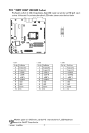
When the system is in S4/S5 mode, only the USB ports routed to the F_USB1 header can support the ON/OFF Charge function.
Hardware Installation
- 21 -
Manual - Page 23
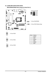
12) JCOM3/JRS14/JRS15/JRS21/JRS19 (RS232/RS422/RS485 Select Header for Serial Port 3)
JCOM3
JRS14 JRS15 JRS21 JRS19
42
1
41 1
1-2 Close: RS422/RS485 2-3 Close: RS232 (Default setting)
21 1-2 Close: RS232
65
21 3-4 Close: RS422
65
21 5-6 Close: RS485
65
Pin No. 1 2 3 4 5 6
Definition RXD232 RXD3 RXD422 RXD3 RXD485 RXD3
- 23 -
Hardware Installation
Manual - Page 24
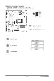
14) JCOM5/JRS23/JRS22/JRS27/JRS29 (RS232/RS422/RS485 Select Header for Serial Port 4)
42
JCOM5
JRS23 JRS22 JRS27 JRS29
41
1
1-2 Close: RS422/RS485
1
2-3 Close: RS232 (Default setting)
56 1-2 Close: RS232
12
56 3-4 Close: RS422
12 56
5-6 Close: RS485 12
Pin No. 1 2 3 4 5 6
Definition RXD232 RXD4 RXD422 RXD4 RXD485 RXD4
- 24 -
Hardware Installation
Manual - Page 25
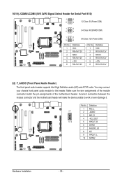
... Serial Port 9/10)
1
2
5
6
1-2 Close: 5V (Power COM)
JCOM6 JCOM8
1
2
5
6
3-4 Close: RI (STAND COM)
1
2
5
6
5-6 Close: 12V (Power COM)
Pin No. 1 2 3 4 5 6
Definition VCC RI9-/5V/12V NRI9RI9-/5V/12V +12V RI9-/5V/12V
Pin No. 1 2 3 4 5 6
Definition VCC RI10-/5V/12V NRI10RI10-/5V/12V +12V RI10-/5V/12V
22) F_AUDIO (Front Panel Audio Header)
The front panel audio header supports...
Manual - Page 27
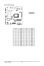
25) LPT (LPT Connector)
30
2
29
1
Pin No. 1 2 3 4 5 6 7 8 9 10 11 12 13 14 15
Definition
42 STB-
PD3 GND GND
41AFD-
PD4 GND GND PD0 PD5 GND GND ERRPD6 GND
Pin No. 16 17 18 19 20 21 22 23 24 25 26 27 28 29 30
Definition GND PD1 PD7 GND GND INITACKGND GND PD2 BUSY GND PE SLINSLCT
Hardware Installation
- 27 -
Manual - Page 28
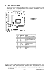
... below. Note the positive and negative pins before connecting the cables.
2
10
1
9
Pin No. 1 2 3 4 5 6 7 8 9 10
Signal Name HD+ MPD+ HD- GND GND -PWRBT_F -SYS_RST GND NC NC
Definition Hard Disk LED Signal anode (+) Power LED Signal anode (+) Hard Disk LED Signal cathode(-) Ground Ground Power Button cathode(-) Reset Button Ground No connect No Pin
The...