Gigabyte MBBZ1AI driver and firmware

Related Gigabyte MBBZ1AI Manual Pages
Download the free PDF manual for Gigabyte MBBZ1AI and other Gigabyte manuals at ManualOwl.com
Manual - Page 3
... Installing a Memory 11 1-4 Back Panel Connectors 12 1-5 Internal Connectors 14
Chapter 2 BIOS Setup 24 2-1 The Main Menu 26 2-2 Advanced Menu 28
2-2-1 ACPI Settings...29 2-2-2 CPU Configuration 30 2-2-3 SATA Configuration 32 2-2-4 USB Configuration 33 2-2-5 F81214 First Super IO Configuration 34 2-2-6 F81214 Second Super IO Configuration 36 2-2-7 Network Stack...38 2-3 Chipset Menu...
Manual - Page 4
Box Contents
MBBZ1AI motherboard Driver CD Two SATA cables I/O Shield
• The box contents above are for reference only and the actual items shall depend on the product package you obtain. The box contents are subject to change without notice.
• The motherboard image is for reference only.
- 4 -
Manual - Page 6
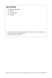
... USB 2.0 ports
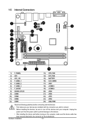
(buttom) USB 2.0 ports USB 3.0 ports HDMI port VGA port (top) / DVI-D port (buttom) Mini PCI Express connector 4 pin power connector Embedded porcessor CPU fan connector DDR3 SO-DIMM slot DDR3 SO-DIMM slot System fan connector 24 pin power connector Front panel header Battery socket Clear CMOS jumper AMD Hudsion-M1 Fusion Controller
Hub (A50M) SATA 6Gb/s connectors Serial port cable...
Manual - Page 7
... a motherboard, CPU or memory. If you do not have an ESD wrist strap, keep your hands dry and first touch a metal object to eliminate static electricity. • Prior to installing the motherboard, please have it on top of an antistatic pad or within an electrostatic shielding container. • Before unplugging the power supply cable from the motherboard, make...
Manual - Page 8
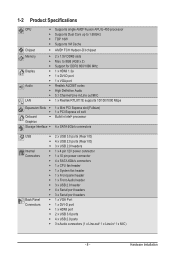
... 10 pin power connector ŠŠ 4 x SATA 6Gb/s connectors ŠŠ 1 x CPU fan header ŠŠ 1 x System fan header ŠŠ 1 x Front panel header ŠŠ 1 x Front Audio header ŠŠ 3 x USB 2.0 header ŠŠ 4 x Serial port headers ŠŠ 3 x Serial port headers ŠŠ 1 x VGA Port ŠŠ 1 x DVI-D port ŠŠ 1 x HDMI port ŠŠ...
Manual - Page 9
I/O Controller ŠŠ iTE IT81214 chip
Hardware Monitor BIOS
ŠŠ CPU/System temperature detection ŠŠ CPU fan speed detection ŠŠ 1 x 16 Mbit flash ŠŠ AMI BIOS
Form Factor ŠŠ Mini ITX Form Factor; 170cm x 170cm
* GIGABYTE reserves the right to make any changes to the product specifications and product-related information without prior...
Manual - Page 10
... you begin to install the memory: • Make sure that the motherboard supports the memory. It is recommended that memory of the
same capacity, brand, speed, and chips be used. • Always turn off the computer and unplug the power cord from the power outlet before installing
the memory to prevent hardware damage. • Memory modules have a foolproof design. A memory module can be...
Manual - Page 11
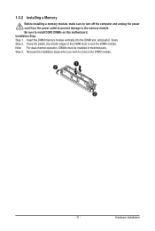
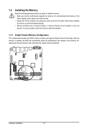
1-3-2 Installing a Memory
Before installing a memory module, make sure to turn off the computer and unplug the power cord from the power outlet to prevent damage to the memory module. Be sure to install DDR3 DIMMs on this motherboard. Installation Step: Step 1. Insert the DIMM memory module vertically into the DIMM slot, and push it down. Step 2. Close the plastic clip at both edges...
Manual - Page 12
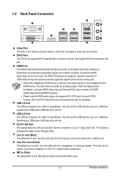
... Setup, then set Onboard VGA output connect to D-SUB/ HDMI under Advanced BIOS Features..
• Please note the HDMI audio output only supports AC3, DTS and 2-channel-LPCM formats. (AC3 and DTS require the use of an external decoder for decoding.)
USB 3.0 Port The USB port supports the USB 3.0 specification. Use this port for USB devices such as a USB keyboard/mouse, USB printer, USB flash drive...
Manual - Page 13
... receiving is occurring
Off
No data transmission or receiving is occurring
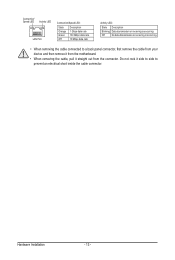
• When removing the cable connected to a back panel connector, first remove the cable from your device and then remove it from the motherboard.
• When removing the cable, pull it straight out from the connector. Do not rock it side to side to...
Manual - Page 14
... connectors you wish to connect.
• Before installing the devices, be sure to turn off the devices and your computer. Unplug the
power cord from the power outlet to prevent damage to the devices.
• After installing the device and before turning on the computer, make sure the device cable has
been securely attached to the connector on the motherboard.
Hardware Installation
- 14 -
Manual - Page 15
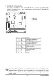
..., speaker, LAN LED sensor and system status indicator on the chassis to this header according to the pin assignments below. Note the positive and negative pins before connecting the cables.
2
10
1
9
Pin No. 1 2 3 4 5 6 7 8 9 10
Signal Name HD+ MPD+ HD- MPD- GND PW+ RESET PW- NC NC
Definition Hard Disk LED Signal anode (+) Power LED...
Manual - Page 16
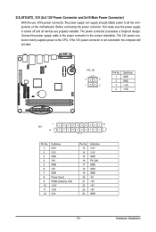
... on the motherboard. Before connecting the power connector, first make sure the power supply is turned off and all devices are properly installed. The power connector possesses a foolproof design. Connect the power supply cable to the power connector in the correct orientation. The 12V power connector mainly supplies power to the CPU. If the 12V power connector is not connected, the computer will...
Manual - Page 17
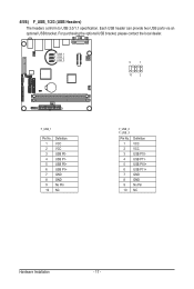
...) The headers conform to USB 2.0/1.1 specification. Each USB header can provide two USB ports via an optional USB bracket. For purchasing the optional USB bracket, please contact the local dealer.
F_USB_1 F_USB_2 F_USB_3
9
1
10
2
F_USB_1
Pin No. 1 2 3 4 5 6 7 8 9 10
Definition VCC VCC USB P0USB P1USB P0+ USB P1+ GND GND No Pin NC
F_USB_2 F_USB_3
Pin No. 1 2 3 4 5 6 7 8 9 10
Definition...
Manual - Page 18
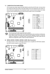
... between the module connector and the motherboard header will make the device unable to work or even damage it.
Pin No. Definition
1 F_MIC2_L
2 GND
12
3 F_MIC2_R
4 -ACZ_DET
5 F_LINE2_R
9 10
6 F_MIC_JD
7 GND
8 No Pin
9 F_LINE2_L
10 F_LINE2__JD
DEBUG PORT
• The front panel audio header supports HD audio by default. • Audio signals will be present on both...
Manual - Page 19
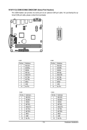
9/10/11/12) COM3/COM4/COM2/COM1 (Serial Port Headers) The COM headers can provide one serial port via an optional COM port cable. For purchasing the optional COM port cable, please contact the local dealer.
21
COM3 10 9
COM4 COM2 COM1
COM1
Pin No. 1 2 3 4 5 6 7... No Pin
COM4
Pin No. 1 2 3 4 5 6 7 8 9 10
Definition NDCDDNDSRDNSIND NRTSDNSOUTD NCTSDNDTDDNRIDGND No Pin
Hardware Installation
Manual - Page 20
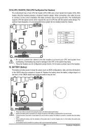
... the ground wire). The motherboard supports CPU fan speed control, which requires the use of a CPU fan with fan speed control design. For optimum heat dissipation, it is recommended that a system fan be installed inside the chassis.
1
1 CPU_FAN
Pin No. 1 2 3 4
Definition GND +12V Sense Speed Control
SYS_FAN
• Be sure to connect fan cables to the fan headers to...
Manual - Page 21
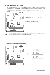
... CMOS values (e.g. date information and BIOS configurations) and reset the CMOS values...Close: Normal operation (Default setting)
1
2-3 Close: Clear CMOS data.
• After clearing the CMOS values and before turning on your computer, be sure to remove... the jumper cap from the jumper. Failure to do so may cause damage to the motherboard.
17) JRS1 ...
Manual - Page 22
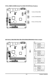
18/19) JCOMC3/JCOMC4 (Serial Port #3/#4 5V/12V/RI Select Headers)
JCOMC3 JCOMC4
21 1-2 Close: 5V (Power COM)
65 21
3-4 Close: RI (STAND COM) 65 21
5-6 Close: 12V (Power COM)
65
20/21/22/23) JRS4/JRS5/JRS3/JRS2 (RS232/RS422/RS485 Mode Select Jumper)
JRS4
JRS3 ...Definition RS422_A -TXD IN RS232 -DTR OUT
JRS5
Pin No. 1 2 3
Definition RS422_B -DTR IN RS232 -DTR OUT
- 22 -
Hardware Installation
Manual - Page 47
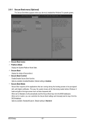
... files being loaded before Windows 8 loads and gets to the login screen have not been tampered with. When set to Standard, it will automatically load the Secure Boot keys form the BIOS databases. When set to Custom, you can customize the Secure Boot settings and manually load its keys from the BIOS database. Options available: Standard/Custom. Default setting is Standard.
BIOS Setup
- 47...