Gigabyte MNIC8CI driver and firmware

Related Gigabyte MNIC8CI Manual Pages
Download the free PDF manual for Gigabyte MNIC8CI and other Gigabyte manuals at ManualOwl.com
Manual - Page 2
... part of this manual may be reproduced, copied, translated, transmitted, or published in any form or by any means without GIGABYTE's prior written permission.
Documentation Classifications
In order to assist in the use of this product, GIGABYTE provides the following types of documentations:
For quick set-up of the product, read the Quick Installation Guide included with...
Manual - Page 3
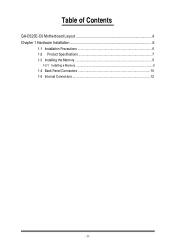
Table of Contents
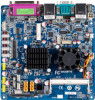
GA-D525E-C6 Motherboard Layout 4 Chapter 1 Hardware Installation 6
1-1 Installation Precautions 6 1-2 Product Specifications 7 1-3 Installing the Memory 9
1-3-1 Installing a Memory ...9
1-4 Back Panel Connectors 10 1-5 Internal Connectors 12
- 3 -
Manual - Page 6
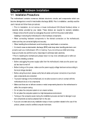
... a motherboard, CPU or memory. If you do not have an ESD wrist strap, keep your hands dry and first touch a metal object to eliminate static electricity. • Prior to installing the motherboard, please have it on top of an antistatic pad or within an electrostatic shielding container. • Before unplugging the power supply cable from the motherboard, make...
Manual - Page 7
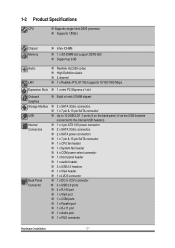
... Specifications
CPU
Supports single Intel® D525 processor
Supports 1.8GHz
Chipset Memory
Audio
LAN Expansion Slots Onboard Graphics Storage Interface USB Internal Connectors
Back Panel Connector
Intel® ICH8M
1 x SO-DIMM slot support DDR3 800 Support up 2GB
Realtek® ALC269 codec High Definition Audio 2 channel 1 x Realtek® RTL 8111Ed supports 10/100/1000 Mbps
1 x mini PCI...
Manual - Page 8
Form Factor
Mini ITX Form Factor; 6.75 inch x 6.75 inch
* GIGABYTE reserves the right to make any changes to the product specifications and product-related information without prior notice.
- 8 -
Hardware Installation
Manual - Page 9
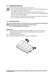
... you begin to install the memory: • Make sure that the motherboard supports the memory. It is recommended that memory of the
same capacity, brand, speed, and chips be used. (Go to GIGABYTE's website for the latest supported memory speeds and memory modules.) • Always turn off the computer and unplug the power cord from the power outlet before installing the memory to prevent hardware...
Manual - Page 10
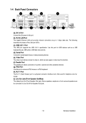
...DC power to this port.
(b). RJ-45 LAN Port
The Gigabit Ethernet LAN port provides Internet connection at up to 1 Gbps data rate. The following describes the states of the LAN port LEDs.
(c). USB 2.0/1.1 Port
The USB port supports the USB 2.0/1.1 specification. Use this port for USB devices such as a USB keyboard/mouse, USB printer, USB flash drive and etc.
(d). Serial Port
Connects to serial-based...
Manual - Page 11
... receiving is occurring
Off
No data transmission or receiving is occurring
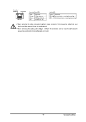
• When removing the cable connected to a back panel connector, first remove the cable from your device and then remove it from the motherboard.
• When removing the cable, pull it straight out from the connector. Do not rock it side to side to...
Manual - Page 12
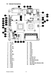
...) JCOM3 26) JCOM5 27) JCOM1 28) COM4 29) LCDPWR_CON 30) BKLTEN_CON 31) JRS2/JRS3/JRS4/JRS5 32) CLR_CMOS1 33) USB_PWR1/USB_PWR2/USB_PWR3 34) LVDS_PWR1
Hardware Installation
- 12 -
Manual - Page 13
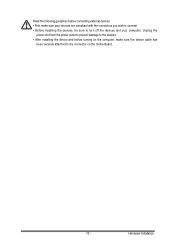
... the connectors you wish to connect. • Before installing the devices, be sure to turn off the devices and your computer. Unplug the
power cord from the power outlet to prevent damage to the devices. • After installing the device and before turning on the computer, make sure the device cable has
been securely attached to the connector on the motherboard.
- 13 -
Hardware...
Manual - Page 14
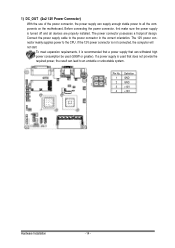
... on the motherboard. Before connecting the power connector, first make sure the power supply is turned off and all devices are properly installed. The power connector possesses a foolproof design. Connect the power supply cable to the power connector in the correct orientation. The 12V power connector mainly supplies power to the CPU. If the 12V power connector is not connected, the computer will...
Manual - Page 15
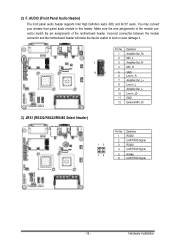
...audio header supports Intel High Definition audio (HD) and AC'97 audio. You may connect your chassis front panel audio module to this header. Make sure the wire assignments of the module connector match the pin assignments of the motherboard header. Incorrect connection between the module connector and the motherboard header will make the device... 6 UART RXD Signal
- 15 -
Hardware Installation
Manual - Page 16
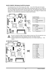
... design. When connecting a fan cable, be sure to connect it in the correct orientation (the black connector wire is the ground wire). The motherboard supports CPU fan speed control, which requires the use of a CPU fan with fan speed control design. For optimum heat dissipation, it is recommended that a system fan be installed inside the chassis.
SYS_FAN 1
SYS_FAN1...
Manual - Page 17
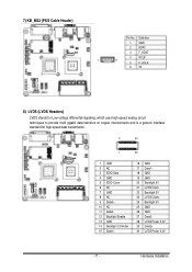
7) KB_MS2 (PS/2 Cable Header)
Pin No. Definition
1 GND
2 KDAT
3 F_KDAT
4 KCLK
1
6
5 F_KCLK
6 5V
8) LVDS (LVDS Headers)
LVDS stands for Low-... 2 NC 3 EDID Data 4 GND 5 EDID Clock 6 NC 7 GND 8 NC 9 Data0+ 10 NC 11 Data012 Backlight Enable 13 GND 14 Backlight Controller 15 Data1+
16 GND 17 Data118 GND 19 GND 20 Backlight 5V 21 LVDS Clock22 Backlight 5V 23 LVDS Clock+ 24 Backlight 5V 25 GND...
Manual - Page 18
... Controller
5 Backlight Enable
1
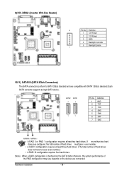
10/11) SATA1/2 (SATA 3Gb/s Connectors)
The SATA connectors conform to SATA 3Gb/s standard and are compatible with SATA 1.5Gb/s standard. Each SATA connector supports a single SATA device.
SATA2
SATA1
SATA2 SATA1
7
7
1
1
Pin No. 1 2 3 4 5 6 7
Definition GND TXP TXN GND RXN RXP GND
• A RAID 0 or RAID 1 configuration requires at least two hard drives...
Manual - Page 19
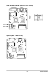
12/13) SATAPW_1/SATAPW_2 (SATA HDD Power Headers)
4
Pin No. Definition
1 +12V
2 GND
1
3 GND
4 5V
SATAPW1 SATAPW2
14) SATA3 (SATA 7+15 Pins Header)
- 19 -
Hardware Installation
Manual - Page 20
... connecting the cables.
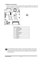
1 9 2 10
Pin No. 1 2 3 4 5 6 7 8 9 10
Pin Definition Stand-by LED Signal Power LED Signal Power Switch Ground LAN Act LED Signal LAN Act LED 5V HDD LED VCC 5V Reset Button Ground
The front panel design may differ by chassis. A front panel module mainly consists of power switch, reset switch, power LED, hard drive activity LED...
Manual - Page 21
...
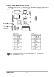
Definition Power (5V) Power (5V) USB DXUSB DYUSB DX+ USB DY+ GND GND No Pin NC
F_USB3
Pin No. 1 2 3 4 5 6 7 8 9 10
Definition Power (5V) Power (5V) USB DXNC USB DX+ NC GND GND No Pin NC
When the system is in S4/S5 mode, only the USB ports routed to the F_USB1 header can support the ON/OFF Charge function.
Hardware Installation
- 21...
Manual - Page 22
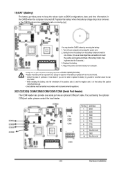
... header can provide one serial port via an optional COM port cable. For purchasing the optional COM port cable, please contact the local dealer.
COM4
COM1 COM5 COM3 COM6
1 9
2 10 COM1 COM3 COM5 COM6
1
9
2
10
COM4
Pin No. 1 2 3 4 5 6 7 8 9 10
Definition DCD DSR RXD RTS TXD CTS DTR RI/+5V/+12V GND RI/+5V/+12V
- 22 -
Hardware Installation
Manual - Page 23
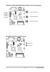
24/25/26/27) JCOM6/JCOM3/JCOM5/JCOM1 (5V/12V/RI for Serial Port Option Header)
JCOMS1 JCOMS5 JCOMS3
JCOMS6
2 6
1 5 2 6
1 5 2 6
1 5
1-2 Close: 5V (Power COM) 3-4 Close: RI (STAND COM) 5-6 Close: 12V (Power COM)
29) LCDPWR_CON (LCD Power ON/OFF Jumper)
Open: Power off. Short: Power On.
- 23 -
Hardware Installation