Lexmark 4079 colorjet printer plus driver and firmware
Drivers and firmware downloads for this Lexmark item
Related Lexmark 4079 colorjet printer plus Manual Pages
Download the free PDF manual for Lexmark 4079 colorjet printer plus and other Lexmark manuals at ManualOwl.com
Service Manual - Page 16
... most. software prograrrs,
nuiEl
!iieleCt the a;propriale p-inte, dr er from that prograrl's I rinsee
,electior menu. i!Vh,Eii i you select a printer fr:rn the I i a
s
r stalled t hrr al lows v documents to be printed correct. y
i)! •I r
l ' the IF1,,1 .4079 printer C Oles not appear on the iist in 'your )rograrl,
niL can Ilse any ("Jill( following printer driver ermilat...
Service Manual - Page 26
...displayed rl the controller board is instal led; the bo :torn ntu-nber is di; pia it the controller board is ,,H!rrio ied
• scrne error coc es are operator -correctable. SI)e page Operator Codes and Messages" on page 2-1C.
• Other codes indicate the printer...code is Jisplayed, and rra beeps are heard Lao< Ir.r the tyml,:rom in the 'Able and take the indicated action.
:1. If you are ...
Service Manual - Page 32
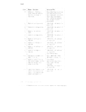
...serial error has
I been displa!,•ed,
e-rcr
reporl'ing is sup; ressed
unti interfa( e parameters
are clangec: or g.rintar . ;
powered...2-26.
ti4 Black ink c a; tricge rct 4 installed
fi b Yellow irk c--.rtridge lot 4 installed
cF, Plage
cartricgc not
4 installed
• "MAP 01 'C: Ink ..:artriage'
on ... it oh
j Go lo "MAP 033( : RAM (Marrioryi" on pe.ce
E3ad Erin itJahly; rnism...
Service Manual - Page 44
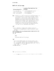
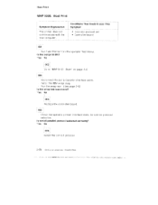
...installed
Conditions That Could Cause. This Symptom
• Cartridge detection t-l sisit or ▪ Cartr -dge sensor cable...servicing with the black...error... card.
With Hnk cartridges instal ...led, check the resistance :Dety, een the
pins designated for each cartridge sensor iloins 1 E nd 3 anc 4: 5
and (3. 7 and Si .
is not used.
(51:ep 003 continues,'
2-24 leivi Color ,Jelp rin e F'S 4079...
Service Manual - Page 46
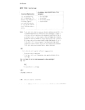
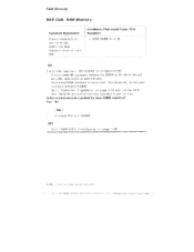
... good cartridge is instal let, or rnav tail to indi c...Ele when the cartridge a empty
Ink cartridge Ink sensor Ink sensor cable Logic board
Note:,
It you...band. Keep the as tern ply on El level plane Vi!h le servicing wits the black car:i idgc end
E.6;viated Cover any o3en ink l...Step 003 cc ntinues
2.26 IBM Color JElpri -:S 4079 HIV, S
II ,
I•1 t
II • 0 0 •
1•t+de i...
Service Manual - Page 75
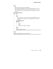
... to 0 V.
Is the voltage correct? Yes No
007 Check continuity on the connector cable between the logic board and the purge sensor. (See page 4-2 for connector location.)
Is continuity correct? Yes No
008 Replace the cables as needed. 009 Replace the logic board.
0101 Install the purge assembly and end the call.
Diagnostic Information 2-55
Service Manual - Page 85
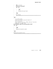
Operator Panel
004 (continued) Is the error corrected? Yes No
1
005 Replace the logic hoard. fj-006 End the call.
007 Turn oft the printer. Instal l the controller board and connect J4 Turn on the printer. Check operation of buttons. LEDs, LCD (see "Controller Diagnostics" on page 2-83)
Do all buttons, LEDs, and LCDs pass their tests? Yes...
Service Manual - Page 87
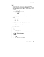
... J4 unplugged - Check the voltage on cable J4 from the power supply. pins 1 -5 (brown to yellow) 5 V pins 3 -5 (red to yellow) 5 V Are the voltages correct? Yes No
008 Turn off the printer. Make sure the controller card EPROM and memory SIMMS are installed and seated correctly. Turn on the printer.
Does the printer complete POST? Yes No
0091 Go to...
Service Manual - Page 90
...set • Control ler board
001 •
Flun TE•isl. Print A lr mr1 the operator test menu. Is the test pilot CPO Yes !No
002 Go to `MAP 010): Start' on page 2-2.
003
Disconnect the ser
interface cable.
Install... the IBM wrap plug.
[tun the wrap test
page 2-83
Is the wrap test succeastul?
"es No
004
Replace the contrriller board.
005
Check the operatoi printer ...
Service Manual - Page 92
.... It error code 960 :pnears, replace the SIMM in J3 wh ch !ishcidd be 4 ME, and conlirJe with the step. Check the RAM installed in the printer. '&.";ee AsseTibh 4-4 for part numbers of these SI MMS. Go to "Controller „agnostics" on page 2-83 and -un the teal:. Note the a rn•tiunt of memory reported...
Service Manual - Page 95
... Sample
Print Head Cleaning Procedures
Normal Cleaning
Long Cleaning
Printing Mode
Power-On Self Test (POST)
Controller Diagnostics .
.... .
Controller Diagnostics Menu
Paper Load Test
Printer Wrap Test
Button Test
LED Test
LCD Test
RAM Test
Last Error
Print Test Page
Clean Heads
Software Version
Defaults
Service Adjustment Mode
2-75 2-76 2-76 2-77 2-77 2-78 2-78 2-78 2-79...
Service Manual - Page 98
Diagnostic /lids
5. Press Select. Th€ display reads C6 Print rest arid pr inting 3 started.
After the nozzle ched< is printed, the printer returns to thH men: rrrcde.
=.:
:t_
1.:gore
...procedures clean out the ink l ines during dag lost c orocedtmes or after new ink parts have been Installed.
Normal Cleaning This head cleaning p -cc;eOure takes abcut 15 seconds.
After cleaning the le acs,...
Service Manual - Page 102
... 7e ard. This beep may be very faint Aihen tnia controller board Is installed.
note:
After the printe- sits idle for approximately 15 :sec:olds, the heads are auto -natically capped and a Star ,:") appc ars in the display. Do no L- im off the printer for long per ocis of tirne until the heads are capped...
Service Manual - Page 103
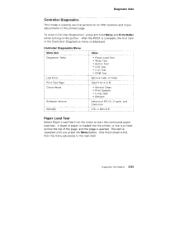
... turning on the printer. After the POST is complete, the first item in the Controller Diagnostics menu is displayed.
Controller Diagnostics Menu Menu Item Diagnostic Tests
Last Error Print Test Page Clean Heads
Software Version Defaults
Value
• Paper Load Test • Wrap Test • Button Test • LED Test • LCD Test • RAM Test
Service code, or Clear...
Service Manual - Page 104
...
Priinter Wrap Test
This tests the serial4arallei comirnunittations interface and displays a message on the display. To perform the wrap test:
1 . Turn the printer o:f. 2. Disconr ect 0 parallel or serial interface cable. 3. Install the wrap 4. Pree3 and hold th, ?. Menu and Print I3uffer buttons whi e y.pu rn
on the printer , 5. Select. Wrap f rcrn the menu. The test runs contind...
Service Manual - Page 105
Diagnostic Aids
Last Error
Select Last Error to display the last error stored in memory. Y Ju can also clear the error codes stored in memory by selecting Clear
Print Test Page
...Software Version
Use this option if you need to know the software level of the various components in the printer.
Defaults
Use this option whenever the controller board is replaced to make sure the national defaults are set...
Service Manual - Page 108
... ,n al:idition to all the usual precautions such as switching off power before rerncyrtng •ogic oards:
Keep the ESD•sensit ive part ... band to t.he system ground pl")ini . This discharges any stet Io electricity in Your" body to the machine.
Hold the ESD-:ens U...iv e parts front being accidental y to ached other personnel. Install machine covers when you are not working on the mach he, ...
Service Manual - Page 117
... Unit . Print Head, Print Head Cover Carriage Card, Carriage Card Holder Cover Print Timing Slit Carriage Encoder and Paper Width Sensor
Encoder Cable Handling Carriage Ribbon Cables
Carriage Cable Handling Carriage cable 19 pin Carriage cable 20 pin
Carriage Shaft, Carriage Belt, and Carriage Ink Supply Power Supply Controller Board and Logic Board Electronic Modules (Assembly 4) Purge Unit
Purge...
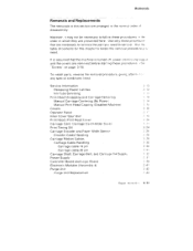
Service Manual - Page 127
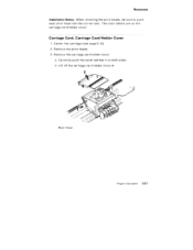
Removals Installation Notes: When installing the print heads, be sure to push each print head into the correct slot. The color letters are on the carriage card holder cover.
Carriage Card, Carriage Card Holder Cover
1. Center the carriage (see page 3-14). 2. Remove the print heads. 3. Remove the carriage card holder cover:
a. Carefully push the small latches 1 on...
Service Manual - Page 131
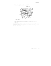
3. Unhook the right end of the timing slit 3. Triangle marks
Removals
Arrow marks
Rear View 4. Draw the print timing slit through the carriage and out of the
machine.
Installation Notes: When installing the timing slit, note that the purge unit side has triangle marks and arrows, which must point upward.
Repair , nformation 3•-25