Sony PCV-J150 - Vaio Desktop Computer driver and firmware
Related Sony PCV-J150 Manual Pages
Download the free PDF manual for Sony PCV-J150 and other Sony manuals at ManualOwl.com
System Reference Manual (primary manual) - Page 2
... IBM Corporation.
All other trademarks are trademarks or registered trademarks of their respective owners.
Owner's Record
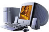
The model number and serial number are located on the back of your VAIO® computer. Record the serial number in the space provided here. Refer to the model and serial number when you call your Sony Service Center.
Model Number: PCV-J150
Serial Number
ii
System Reference Manual (primary manual) - Page 3
....
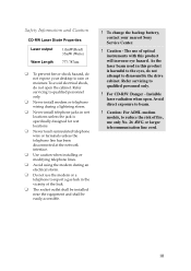
❑ Do not use the modem or a
telephone to report a gas leak in the vicinity of the leak.
❑ The socket outlet shall be installed
near the equipment and shall be easily accessible.
! To change the backup battery, contact your nearest Sony Service Center.
! Caution - The use of optical instruments with this product will increase...
System Reference Manual (primary manual) - Page 5

... of Conformity
Trade Name:
SONY
Model No.:
PCV-J150
Responsible Party: Sony Electronics Inc.
Address:
680 Kinderkamack Rd Oradell, NJ 07649
Telephone:
201-930-6972
This phone number is for FCC-related matters only.
This device complies with Part 15 of FCC Rules. Operation is subject to the two following conditions:
(1) This device may not cause harmful interference...
System Reference Manual (primary manual) - Page 6
... necessary modifications in order to maintain uninterrupted service.
If trouble is experienced with this modem, for repair or warranty information, please contact 1-888-4SONY-PC, or write to the Sony Customer Information Center, 12451 Gateway Blvd., Fort Myers, FL 33913. If the trouble is causing harm to the telephone network, the telephone company may request that...
System Reference Manual (primary manual) - Page 11
...
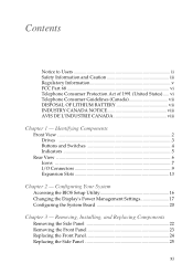
Chapter 1 - Identifying Components
Front View 2 Drives 3 Buttons and Switches 4 Indicators 5
Rear View ...6 Icons ...7 I/O Connectors 9 Expansion Slots 13
Chapter 2 - Configuring Your System
Accessing the BIOS Setup Utility 16 Changing the Display's Power Management Settings 17 Configuring the System Board 20
Chapter 3 - Removing, Installing, and Replacing Components
Removing the Side...
System Reference Manual (primary manual) - Page 12
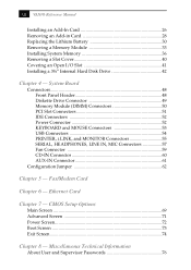
...) Connectors 50 PCI Slot Connectors 51 IDE Connectors 52 Power Connector 52 KEYBOARD and MOUSE Connectors 53 USB Connectors 54 PRINTER, i.LINK, and MONITOR Connectors 55 SERIAL, HEADPHONES, LINE IN, MIC Connectors 57 Fan Connector 59 CD-IN Connector 60 AUX-IN Connector 61
Configuration Jumper 62
Chapter 5 - Fax/Modem Card
Chapter 6 - Ethernet Card
Chapter 7 - CMOS Setup Options
Main...
System Reference Manual (primary manual) - Page 26
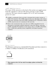
12 VAIO® Reference Manual
i.LINK® (IEEE1394) Connector The 6-pin i.LINK connector on the back of the system can supply power from the computer to a device if the device also has a 6-pin i.LINK connector. The 6-pin connector supplies 10V to 12V and a maximum power of 6 watts.
✍ i.LINK is a trademark of Sony used only to designate that a product...
System Reference Manual (primary manual) - Page 30
16 VAIO® Reference Manual
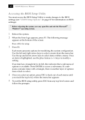
Accessing the BIOS Setup Utility
You must access the BIOS Setup Utility to make changes to the BIOS settings (see "CMOS Setup Options" on page 67 for information on BIOS settings).
! Before rebooting the system, save any open files and exit the Microsoft®
Windows® operating system.
1 Reboot the system. 2 When the Sony logo appears, press F3. The...
System Reference Manual (primary manual) - Page 34
...-Volatile RAM (NVRAM) settings are only cleared if the checksum test returns false. Access to specific setup fields is controlled by a supervisor password or user password. The Clear CMOS mode removes the password that is stored in CMOS. No other parameters are cleared.
✍ The configuration jumpers should never need changing unless otherwise
directed by a technical support or service...
System Reference Manual (primary manual) - Page 35
Chapter 3 Removing, Installing, and Replacing Components
This chapter describes removing, installing, and replacing major components for upgrading, reconfiguring, and troubleshooting the components.
! Before opening the system unit, save any open files, exit the Windows®
operating system, turn off the power of the computer and all attached peripherals, and then unplug the power cord.
21
System Reference Manual (primary manual) - Page 37
... Replacing Components
23
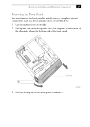
Removing the Front Panel
You must remove the front panel to install, remove, or replace internal components such as a drive, diskette drive, or CD-RW drive.
1 Lay the system down on its side.
2 Pull up and out on the two plastic tabs (1 in diagram) at the bottom of
the chassis to...
System Reference Manual (primary manual) - Page 39
Removing, Installing, and Replacing Components
25
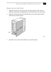
Replacing the Side Panel
1 Align the bottom of the side panel with the bottom of the chassis,
with the side panel extending about ½ inch from the rear of the unit.
2 Slide the side panel forward until the lip on the side panel is flush
with the rear of the chassis.
3 Insert the screw (removed earlier) to secure the panel.
KY0067.VSD
System Reference Manual (primary manual) - Page 40
26 VAIO® Reference Manual
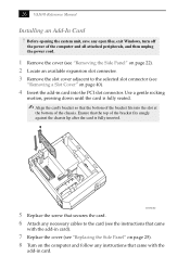
Installing an Add-In Card ! Before opening the system unit, save any open files, exit Windows, turn off
the power of the computer and all attached peripherals, and then unplug the power cord....4 Insert the add-in card into the PCI slot connector. Use a gentle rocking
motion, pressing down until the card is fully seated.
✍ Align the card's bracket so that the ...
System Reference Manual (primary manual) - Page 41
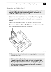
... system unit, save any open files, exit the Windows®
operating system, turn off the power of the computer and all attached peripherals, and then unplug the power cord.
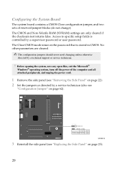
1 Remove the cover (see "Removing the Side Panel" on page 22). 2 Disconnect any cables attached to the add-in card you want to
remove.
3 Remove the screw...
System Reference Manual (primary manual) - Page 42
28 VAIO® Reference Manual
5 If you do not replace the card or install another add-in card, install a
slot cover over the vacant slot at the rear of the chassis (see "Covering an Open I/O Slot" on page 41).
6 Replace the cover (see "Replacing the Side Panel" on page 25).
System Reference Manual (primary manual) - Page 43
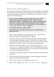
... lithium battery if your computer consistently loses the date or time settings after turning it off. The lithium battery has a typical life of three years, after which the battery may be too weak to power the CMOS memory.
! When you remove the lithium battery, all values stored in the CMOS
memory (BIOS setup values and Plug and...
System Reference Manual (primary manual) - Page 45
Removing, Installing, and Replacing Components
31
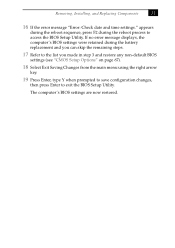
16 If the error message "Error: Check date and time settings." appears
during the reboot sequence, press F2 during the reboot process to access the BIOS Setup Utility. If no error message displays, the computer's BIOS settings were retained during the battery replacement and you can skip the remaining steps.
17 Refer to the list you...
System Reference Manual (primary manual) - Page 46
32 VAIO® Reference Manual
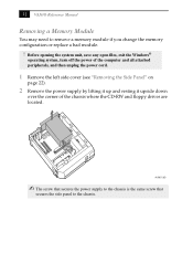
Removing a Memory Module
You may need to remove a memory module if you change the memory configuration or replace a bad module.
! Before opening the system unit, save any open files, exit the Windows®
operating system, turn off the power of the computer and all attached peripherals, and then unplug the power cord.
1 Remove the left...
System Reference Manual (primary manual) - Page 49
... Replacing Components
35
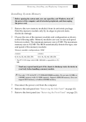
Installing System Memory
! Before opening the system unit, save any open files, exit Windows, turn off
the power of the computer and all attached peripherals, and then unplug the power cord.
1 Remove the new memory module(s) from its anti-static package.
Hold the memory module only by its edges to prevent staticelectricity damage.
2 Choose the...
System Reference Manual (primary manual) - Page 55

... already have a second hard disk drive.
Your system can support ATA-33, ATA-66, or ATA-100 hard disk drives. The drive you install must not require front panel access. The hard disk drive access light blinks when either internal drive is active.
! Before opening the system unit, save any open files, exit Windows, turn off
the power of the computer and all attached peripherals, and...