Toshiba 100CT driver and firmware

Related Toshiba 100CT Manual Pages
Download the free PDF manual for Toshiba 100CT and other Toshiba manuals at ManualOwl.com
User Manual - Page 1
... the use of the information contained herein.
Toshiba Libretto 100CT Maintenance Manual
First edition February 1998
Disclaimer
The information contained in this manual is subject to change without notice.
Toshiba Corporation and Toshiba America Information Systems, Inc., assume no liability for damages incurred directly or indirectly from errors, omissions, or discrepancies in connection with the...
User Manual - Page 2
...-140
Preface
This maintenance manual describes how to perform hardware service maintenance for the Toshiba Personal Computer Libretto 100CT. The procedures described in this manual are intended to help service technicians isolate faulty Field Replaceable Units (FRUs) and replace them in the field.
SAFETY PRECAUTIONS
Four types of messages are used in this manual to bring important information...
User Manual - Page 12
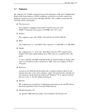
... have special functions in Microsoft® Windows® 95. It supports software that uses a 101- or 102-key enhanced keyboard.
Batteries
The computer has two batteries a Lithium-Ion main battery pack and RTC battery that backs up the Real Time Clock and CMOS memory.
Expansion memory slot
An optional 32MB memory module can be installed in the memory slot.
1-1
User Manual - Page 13
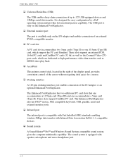
... support CardBus PC card. The Enhanced Port Replicator also has PS/2™ mouse, PS/2 compatible keyboard, USB, parallel, serial and external monitor ports.
Infrared port
The infrared port is compatible with Fast InfraRed (FIR) standards enabling wireless 4Mbps data transfer with Infrared Data Association (IrDA) 1.1 compatible devices.
Sound system
A Sound Blaster™ Pro™ and Windows...
User Manual - Page 25
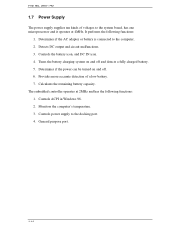
... a fully charged battery. 5. Determines if the power can be turned on and off. 6. Provides more accurate detection of a low battery. 7. Calculates the remaining battery capacity. The embedded controller operates at 2MHz and has the following functions: 1. Controls ACPI in Windows 98. 2. Monitors the computer's temperature. 3. Controls power supply to the docking port. 4. General purpose port.
1-14
User Manual - Page 34
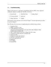
...MS-DOS system disk(s)
(You must install the following onto the disk: SYS.COM, FORMAT.COM, FDISK.COM and FDISK.EXE) 4. 2DD or 2HD formatted work disk for floppy disk drive testing 5. Cleaning kit for floppy disk drive troubleshooting 6. Printer port LED 7. Printer port wraparound connector 8. Serial port wraparound connector 9. PC card wraparound card 10. Multimeter 11. I/O Adapter 12. External FDD...
User Manual - Page 35

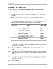
... step in the flowchart in Figure 2-1: Connect the printer port wraparound board (F31PRT), then turn the POWER switch on. The computer will override the password function by erasing the current password.
®
Verify with the customer that Toshiba Windows 95 is installed on the hard disk. NonToshiba operating systems can cause the computer to malfunction. Make sure all optional equipment is...
User Manual - Page 40
...
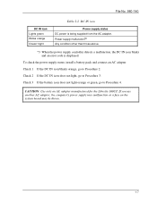
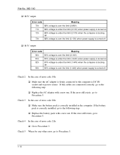
Table 2-2 DC IN icon
Power supply status DC power is being supplied from the AC adapter. Power supply malfunction*3 Any condition other than those above.
*3 When the power supply controller detects a malfunction, the DC IN icon blinks and an error code is displayed.
To check the power supply status, install a battery pack and connect an AC adapter. Check 1 If the DC...
User Manual - Page 43
... DC IN socket and to power source. If this cables are connected correctly, go to the following step:
Replace the AC adapter with a new one. If the error still exists, go to Procedure 5.
Check 3 In the case of error code 20h:
Make sure the battery pack is correctly installed in the computer. If the battery pack is...
User Manual - Page 45
... are firmly plugged into the DC IN socket and the wall outlet. If these cables are connected correctly, replace the AC power cord and AC adapter.
Check 2 Make sure the battery is properly installed. If the battery is properly installed, replace it with a new one.
Check 3 The battery pack may be completely discharged. Wait a few...
User Manual - Page 48
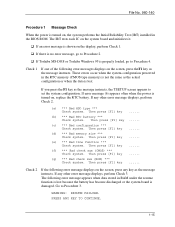
... the power is turned on, the system performs the Initial Reliability Test (IRT) installed in the BIOS ROM. The IRT tests each IC on the system board and initializes it.
If an error message is shown on the display, perform Check 1. If there is no error message, go to Procedure 2.
If Toshiba MS-DOS or Toshiba Windows 95 is properly loaded, go...
User Manual - Page 49
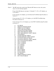
...PARITY ERROR (8) VRAM ERROR (9) SYSTEM MEMORY ERROR (10) SYSTEM MEMORY PARITY ERROR (11) EXTENDED MEMORY ERROR (12) EXTENDED MEMORY PARITY ERROR (13) DMA PAGE REGISTER ERROR (14) DMAC #1 ERROR (15) DMAC #2 ERROR (16) PIC #1 ERROR (17) PIC #2 ERROR (18) KBC ERROR (19) HDC ERROR (20) HDD #0 ERROR (21) HDD #1 ERROR (22) NO FDD ERROR (23) FDC ERROR (24) TIMER INTERRUPT ERROR (25) RTC UPDATE ERROR
1-16
User Manual - Page 54
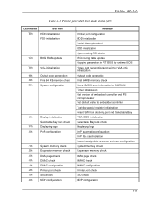
...Message Printer port configuration HDD initialization Serial interrupt control FDD initialization Open closing PCI device IRQ routing table update Copying parameter in IRT BIOS to runtime BIOS Video card recognition and wait for VGA chip initialization Output code generation First 64 KB memory check Store CMOS error information to SM-RAM Timer initialization Get version of embedded controller and...
User Manual - Page 55
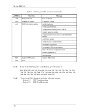
... password External I/O check Set font address Set shadow RAM size Set expansion memory size to CMOS System resource update Set extended memory size to runtime BIOS for INT15h ACPI table update Set SCT area to runtime BIOS Set battery save mode Send date to PS microprocessor Close PCI device configuration area Protect system BIOS Cache control System ROM check
Check 1 If any of the following error...
User Manual - Page 56
... test status values in Table 2-4, perform
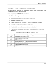
Procedure 5. Table 2-4 Printer port LED Resume mode error status
Error status F1H F2H F3H F4H F5H F7H F8H
Meaning of status System BIOS RAM checksum error External display card is connected. HDD was installed. SMRAM checksum error or memory error during suspend Conventional memory checksum error Extended memory checksum error PnP RAM checksum error
1-23
User Manual - Page 60
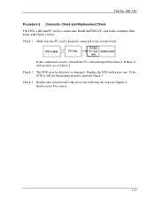
... Replacement Check The FDD, cable and PC card is a single unit. Install the FDD's PC card in the computer, then begin with Check 1 below. Check 1 Make sure the PC card is properly connected to the system board.
If the connection is loose, reinstall the PC card and repeat Procedure 2. If there is still an error, go to Check 2. Check...
User Manual - Page 61
... device. If the customer has not or cannot perform the backup, create backup disks as described below. Check to see if the Microsoft Create System Disks Tools (MSCSD.EXE) still exists in the System Tools Folder. (This tool can be used only once.) If it exists, use it to back up the preinstalled software...
User Manual - Page 101
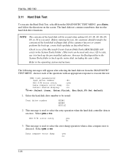
... drive number
:#1
HDC F/W error retry
:yes
Data compare error dump :no
Detail status display
:no
Select items, Enter:Finish, Esc:Exit,F5:Set default
1. Select the hard disk drive number to be tested:
Test drive number
HDD#1 HDD#2 HDD1&2
2. This message is used to select the retry operation when the hard disk controller detects an error. Select yes or no.
HDC F/W error...
User Manual - Page 138
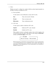
... cache write policy. The options for this setting are Write-back (default) and Write-through for CPU cache.
Write-back policy provides better system performance, because main memory is accessed only when necessary to update the cache contents with changes in main memory. Write-through policy accesses main memory every timedata is handled by the processor.
3-63
User Manual - Page 146
...-140
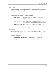
10. PCI Bus
This option displays the interrupt request level for the CardBus in the computer. It is for information only and cannot be changed.
11. PC Card
This option lets you set the PC Card Controller mode.
Auto-Selected
Use this setting for all PC Card if you are using Windows 95. (Default)
Card Bus/16 bit
If the card does not...