Gigabyte MSH61PI driver and firmware

Related Gigabyte MSH61PI Manual Pages
Download the free PDF manual for Gigabyte MSH61PI and other Gigabyte manuals at ManualOwl.com
Manual - Page 2

... of this manual may be reproduced, copied, translated, transmitted, or published in any form or by any means without GIGABYTE's prior written permission.
Documentation Classifications In order to assist in the use of this product, GIGABYTE provides the following types of documentations:
For quick set-up of the product, read the Quick Installation Guide included with...
Manual - Page 3
... Installing a Memory 13 1-5 Back Panel Connectors 14 1-6 Internal Connectors 16
Chapter 2 BIOS Setup 25 2-1 The Main Menu 27 2-2 Advanced Menu 29
2-2-1 ACPI Settings...30 2-2-2 CPU Configuration 31 2-2-2-1 Socket 0 CPU Information 34 2-2-3 SATA Configuration 35 2-2-4 Acoustic Management Configuration 37 2-2-5 Intel IGD SWSCI OpRegion 38 2-2-6 Intel TXT(LT) Configuration 40 2-2-7 USB...
Manual - Page 4

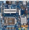
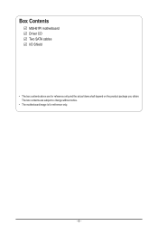
Box Contents
MSH61PI motherboard Driver CD Two SATA cables I/O Shield
• The box contents above are for reference only and the actual items shall depend on the product package you obtain. The box contents are subject to change without notice.
• The motherboard image is for reference only.
- 4 -
Manual - Page 8
... of this manual may be reproduced, copied, translated, transmitted, or published in any form or by any means without GIGABYTE's prior written permission.
Documentation Classifications In order to assist in the use of this product, GIGABYTE provides the following types of documentations:
For quick set-up of the product, read the Quick Installation Guide included with...
Manual - Page 9
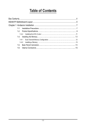
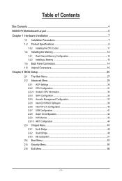
Table of Contents
Box Contents...4 MSH61PI Motherboard Layout 5 Chapter 1 Hardware Installation 7
1-1 Installation Precautions 7 1-2 Product Specifications 8
1-3-2 Installing the CPU Cooler 11 1-4 Installing the Memory 12
1-4-1 Dual Channel Memory Configuration 12 1-4-2 Installing a Memory 13 1-5 Back Panel Connectors 14 1-6 Internal Connectors 16
- 3 -
Manual - Page 10
Box Contents
MSH61PI motherboard Driver CD Two SATA cables I/O Shield
• The box contents above are for reference only and the actual items shall depend on the product package you obtain. The box contents are subject to change without notice.
• The motherboard image is for reference only.
- 4 -
Manual - Page 13
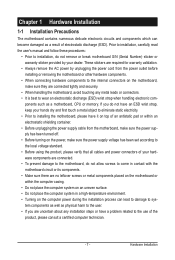
... a motherboard, CPU or memory. If you do not have an ESD wrist strap, keep your hands dry and first touch a metal object to eliminate static electricity. • Prior to installing the motherboard, please have it on top of an antistatic pad or within an electrostatic shielding container. • Before unplugging the power supply cable from the motherboard, make...
Manual - Page 14
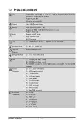
... MHz memory modules ŠŠ Support Up to 4GB ŠŠ Realtek ALC887 codec ŠŠ High Definition Audio ŠŠ 2/4/5.1-channel ŠŠ 1 x Realtek RTL8111E-VL-CG supports 10/100/1000 Mbps
Expansion Slots ŠŠ 1 x Mini PCI Express slot
Onboard
ŠŠ Build in Intel® processor
Graphics
Storage Interface ŠŠ 2 x SATA 3Gb/s connectors
USB...
Manual - Page 15
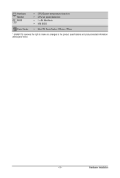
Hardware Monitor BIOS
ŠŠ CPU/System temperature detection ŠŠ CPU fan speed detection ŠŠ 1 x 64 Mbit flash ŠŠ AMI BIOS
Form Factor ŠŠ Mini ITX Form Factor; 170cm x 170cm
* GIGABYTE reserves the right to make any changes to the product specifications and product-related information without prior notice.
- 9 -
Hardware Installation
Manual - Page 16
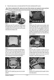
B. Follow the steps below to correctly install the CPU into the motherboard CPU socket.
Before installing the CPU, make sure to turn off the computer and unplug the power cord from the power outlet power plug to prevent any damage to prevent damage to the CPU.
Step 1: Gently press the CPU socket lever handle down and away from the socket with your finger...
Manual - Page 17
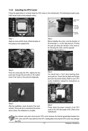
... closely. (Refer to your CPU cooler installation manual for instructions on installing the cooler.)
Step 5:
After the installation, check the back of the motherboard. If the push pin is inserted as the picture above shows, the installation is complete.
Step 6:
Finally, attach the power connector of the CPU cooler to the CPU fan header (CPU_FAN) on the motherboard.
Use extreme care when...
Manual - Page 18
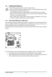
... you begin to install the memory: • Make sure that the motherboard supports the memory. It is recommended that memory of the
same capacity, brand, speed, and chips be used. (Go to GIGABYTE's website for the latest supported memory speeds and memory modules.) • Always turn off the computer and unplug the power cord from the power outlet before installing the memory to prevent hardware...
Manual - Page 19
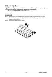
1-4-2 Installing a Memory
Before installing a memory module, make sure to turn off the computer and unplug the power cord from the power outlet to prevent damage to the memory module. Be sure to install DDR3 DIMMs on this motherboard.
Installation Step: Installation Step: Step 1. Align the memory with the DIMM module and insert the DIMM memory module into the DIM slot.
Please note that memory ...
Manual - Page 20
... Setup, then set Onboard VGA output connect to D-SUB/ HDMI under Advanced BIOS Features..
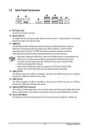
• Please note the HDMI audio output only supports AC3, DTS and 2-channel-LPCM formats. (AC3 and DTS require the use of an external decoder for decoding.)
USB 2.0 Port The USB port supports the USB 2.0 specification. Use this port for USB devices such as a USB keyboard/mouse, USB printer, USB flash drive...
Manual - Page 21
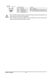
... receiving is occurring
Off
No data transmission or receiving is occurring
• When removing the cable connected to a back panel connector, first remove the cable from your device and then remove it from the motherboard.
• When removing the cable, pull it straight out from the connector. Do not rock it side to side to...
Manual - Page 22
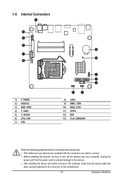
... the connectors you wish to connect. • Before installing the devices, be sure to turn off the devices and your computer. Unplug the
power cord from the power outlet to prevent damage to the devices. • After installing the device and before turning on the computer, make sure the device cable has
been securely attached to the connector on the motherboard.
- 16 -
Hardware...
Manual - Page 23
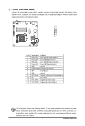
... pins before connecting the cables.
12 11
21
Pin No. 1 2 3 4 5 6 7 8 9 10 11 12
Signal Name Definition HDD LED + Hard Disk LED Signal anode (+) Power LED+ Power LED Signal anode (+) HDD LED - Hard Disk LED Signal cathode(-) Power LED- Power LED Signal cathode(-) GND Ground Power Switch+ Power Button anode (+) RST Reset Button GND Ground LED_WLAN Wireless LAN active LED Signal anode...
Manual - Page 24
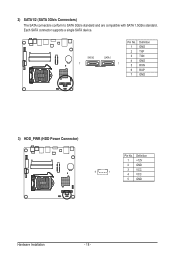
2) SATA1/2 (SATA 3Gb/s Connectors) The SATA connectors conform to SATA 3Gb/s standard and are compatible with SATA 1.5Gb/s standard. Each SATA connector supports a single SATA device.
SATA2 7
SATA1 1
Pin No. 1 2 3 4 5 6 7
Definition GND TXP TXN GND RXN RXP GND
3) HDD_PWR (HDD Power Connector)
5
1
Pin No. 1 2 3 4 5
Definition +12V GND VCC VCC GND
Hardware Installation
- 18 -
Manual - Page 25
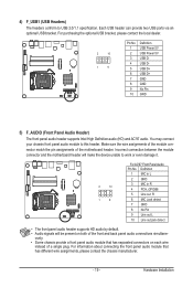
... panel audio header supports Intel High Definition audio (HD) and AC'97 audio. You may connect
your chassis front panel audio module toMthOiDsEhMeader. Make sure the wire assignments of the module con-
nector
match
the
pin
assignments
of
theF_mAUoDthIOerboard
header.
Incorrect
connection
between the
Smart
module
Card Reader
connector and the motherboard header will make the device...
Manual - Page 40
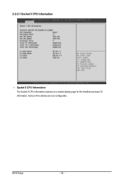
2-2-2-1 Socket 0 CPU Information
Spcket 0 CPU Information: The Socket 0 CPU information submenu is a simple display page for the installed processor ID information. Items on this window are non-configurable.
BIOS Setup
- 34 -