HP Chromebook 11-2100 driver and firmware
Drivers and firmware downloads for this Hewlett-Packard item
Related HP Chromebook 11-2100 Manual Pages
Download the free PDF manual for HP Chromebook 11-2100 and other HP manuals at ManualOwl.com
Maintenance and Service Guide - Page 2
...: 780446-002
Product notice
This guide describes features that are common to most models. Some features may not be available on your computer.
Not all features are available in all editions of Windows 8. This computer may require upgraded and/or separately purchased hardware, drivers, and/or software to take full advantage of Windows 8 functionality. See for http://www...
Maintenance and Service Guide - Page 25
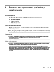
...replacement procedures: ● Flat-bladed screw driver ● Magnetic screw driver ● Phillips P0 screw driver
Service considerations
The following sections include some of ...instructions.
Cables and connectors
CAUTION: When servicing the computer, be sure that cables are placed in their proper locations during the reassembly process. Improper cable placement can damage the computer. Cables...
Maintenance and Service Guide - Page 27
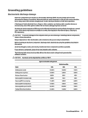
... Networks built into many integrated circuits provide some protection, but in many cases, ESD contains enough power to alter device ...computer when you are removing or installing internal components, observe these precautions:
Keep components in their electrostatic-safe containers until you are ready to install... V 12,000 V 6,000 V 2,000 V 11,500 V 14,500 V 26,500 V 21,000 V
Relative humidity 40%
15,...
Maintenance and Service Guide - Page 28
... work surface and use properly grounded tools and equipment. ● Use conductive field service tools, such as cutters, screw drivers, and vacuums. ● When fixtures must directly contact dissipative surfaces, use fixtures ...leads, or circuitry. ● Turn off power and input signals before inserting or removing connectors or test equipment.
22 Chapter 4 Removal and ...
Maintenance and Service Guide - Page 31
... rubber feet, remove the protective backing from the rubber feet and install them in the locations indicated in the above illustration.
Keyboard/top cover
Description
For...061
For use in the United Kingdom
783090-291
For use in the United States
For use only on HP Chromebook 11 G3 computer models:
788639-A41
For use in Latin America
788639-DB1
For use in the Netherlands
788639-DH1
For use...
Maintenance and Service Guide - Page 32
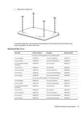
... board on page 32) are removed from the defective keyboard/top cover and installed on the replacement keyboard/top cover. Remove the keyboard/top cover: 1. Remove the two rubber screw covers (1).
NOTE: The rubber screw covers are included in the Rubber Kit, spare part numbers: ● 762581-001-For use only on HP Chromebook 11...
Maintenance and Service Guide - Page 36
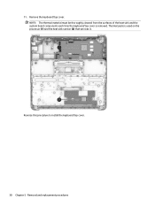
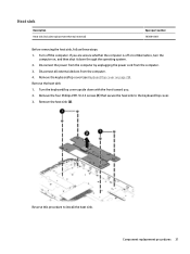
11. Remove the keyboard/top cover. NOTE: The thermal material must be thoroughly cleaned from the surfaces of the heat sink and the system board components each time the keyboard/top cover is removed. Thermal paste is used on the processor (1) and the heat sink section (2) that services it.
Reverse this procedure to install the keyboard/top cover.
30 Chapter 5 Removal and replacement procedures
Maintenance and Service Guide - Page 37
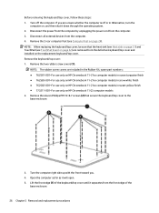
...computer. If you are unsure whether the computer is off or in Hibernation, turn the
computer on, and then shut it down through the operating system. 2. Disconnect the power from the computer by unplugging the power cord from the computer. 3. Disconnect all external devices from the computer... the heat sink (2).
Reverse this procedure to install the heat sink. Component replacement procedures 31
Maintenance and Service Guide - Page 39
Reverse this procedure to install the TouchPad board.
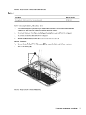
Battery
Description Battery (3-cell, 36-WHr, 3.25-AHr, Li-ion; includes cable)
Spare part number 767068-001
Before removing the battery, follow these steps: 1. Turn off the computer. If you are unsure whether the computer is off or in Hibernation, turn the
computer on, and then shut it down...
Maintenance and Service Guide - Page 41
... illustration.
Reverse this procedure to install the WWAN module.
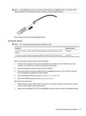
Connector board
NOTE: The connector board spare part kit includes the cable.
Description
For use only on computer models equipped with WWAN capability (includes SD Card Reader slot and SIM slot)
For use only on computer models not equipped with WWAN capability (includes SD Card Reader slot)
Spare part number 785884...
Maintenance and Service Guide - Page 42
... procedure to install the connector board.
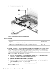
WLAN module
Description Intel Dual Band Wireless-AC 7260 802.11 ac 2×2 WiFi + Bluetooth 4.0 Combo Adapter Intel Dual Band Wireless-N 7260AN 802.11 a/b/g/n 2×2 WiFi + Bluetooth 4.0 Combo Adapter
Spare part number 784645-005 784647-005
CAUTION: To prevent an unresponsive system, replace the wireless module only with a wireless module authorized...
Maintenance and Service Guide - Page 43
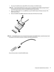
... the terminals on the WLAN module. NOTE: The #1/white WLAN antenna cable connects to the WLAN module #1/Main terminal. The #2/ black WLAN antenna cable connects to the WLAN module #1/Aux terminal.
2. Remove the Phillips PM1.9×4.2... to the terminal on the WLAN module, a protective sleeve must be installed on the antenna connector, as shown in the following illustration.
Reverse this procedure to...
Maintenance and Service Guide - Page 44
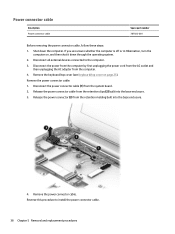
... devices connected to the computer. 3. Disconnect the power from the computer by first unplugging the power cord from the AC outlet and
then unplugging the AC adapter from the computer. 4. Remove the keyboard/top cover (see Keyboard/top cover on page 25). Remove the power connector cable: 1. Disconnect the power connector cable (1) from the system board. 2. Release the power connector cable...
Maintenance and Service Guide - Page 46
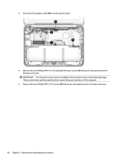
4. Disconnect the speaker cable (4) from the system board.
5. Remove the two Philllips PM2.5×3.7 broad head firmware screws (1) that secure the system board to the base enclosure. IMPORTANT: The firmware screws must be installed in the locations shown in the following image. These screws have specific properties that ensure the proper operation of the computer.
6. Remove the four...
Maintenance and Service Guide - Page 47

7. Remove the system board (3). Reverse this procedure to install the system board.
Component replacement procedures 41
Maintenance and Service Guide - Page 62
...to this
PC
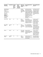
Code is updated when the
memory and is available
configuration system BIOS is updated.
on the HP website; go to
data.
Configuration data and
http://www.hp.com/
settings are input using the support, and select your
Computer Setup (BIOS) or a country. Select Drivers &
custom utility.
Downloads, and then
follow the on-screen
instructions.
NOTE: Writing data to this ROM in an...
Maintenance and Service Guide - Page 63
.... Select Drivers & Downloads, and then follow the on-screen instructions.)
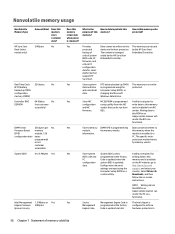
Bluetooth flash 2Mbit
No
802.11 WLAN EEPROM
4 Kbit to 8
No
Kbit
Webcam
64K bit
No
Fingerprint Reader
512 KByte
Yes
flash
Does this memory retain data when power is removed?
What is the
How is data input into this
purpose of this memory?
memory?
How is this memory write protected?
Settings, Provisioning...
Maintenance and Service Guide - Page 64
...OS, the run-time environment allows the loading and execution of software programs from storage devices to provide more functionality, such as advanced hardware diagnostics (with the ability to display more detailed system information) and advanced firmware management and recovery software.
c. Follow the on-screen instructions.
The UEFI BIOS resides on a flash memory chip. A utility is required to...
Maintenance and Service Guide - Page 65
... that most users can use the HP Sure Start default configuration. The default configuration can be customized by advanced users. To access the latest documentation on HP Sure Start, go to http://www.hp.com/support, and select your country. Select Drivers & Downloads, and then follow the on-screen instructions.
Using HP Sure Start (select models only) 59
User Guide - Page 2
... constituting an additional warranty. HP shall not be liable for technical or editorial errors or omissions contained herein.
First Edition: August 2014
Document Part Number: 780447-001
Product notice
This guide describes features that are common to most models. Some features may not be available on your computer.
Software terms
By installing, copying, downloading, or otherwise using any...