HP G60 438NR - Pentium 2 GHz driver and firmware
Drivers and firmware downloads for this Hewlett-Packard item

Related HP G60 438NR Manual Pages
Download the free PDF manual for HP G60 438NR and other HP manuals at ManualOwl.com
Service Guide - Page 2

.... Intel, Celeron, Pentium, and Core are trademarks of Intel Corporation in the U.S. and other countries. Microsoft, Windows, and Windows Vista are U.S. registered trademarks of Microsoft Corporation. SD Logo is a trademark of its proprietor.
The information contained herein is subject to change without notice. The only warranties for HP products and services are set forth in the...
Service Guide - Page 12
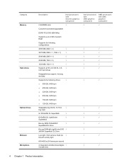
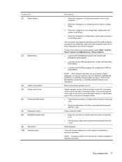
Category Memory
Hard drives
Optical drives Webcam Microphone
Description
Intel processors with discrete graphics subsystem
2 SODIMM slots
√
Customer-accessible/upgradable
DDRII PC2-5300 (800-MHz)
Supports up to 4 GB of system RAM
Supports the following configurations:
4096 MB (2048 × 2)
√
3072 MB (2048 × 1, 1024 × 1)
√
2048 MB (2048 × 1)
√...
Service Guide - Page 13
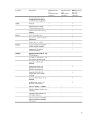
Category
Audio Modem Ethernet Wireless
Description
Intel processors with discrete graphics subsystem
Dual array microphones with
√
software (beam forming, echo
cancellation, noise suppression)
HD audio
√
Supports Windows Vista®
√
Premium Logo requirements
Pavilion-branded Altec Lansing √ speakers
56K V.92 data/fax modem
√
Supports all worldwide ...
Service Guide - Page 15
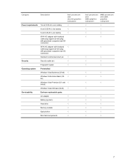
... Vista Premium (32- and √ 64-bit)
Windows Vista Ultimate (64-bit) √
Serviceability
End-user replaceable parts:
AC adapter
√
Battery (system)
√
Hard drive
√
Memory module
√
Optical drive
√
Mini Card components
√
Intel processors with UMA graphics subsystem
AMD processors with UMA graphics subsystem
√
√
√
√...
Service Guide - Page 19
..., briefly press the button to exit Hibernation.
If the computer has stopped responding and Windows® shutdown procedures are ineffective, press and hold the power button for at least 5 seconds to turn off the computer.
To learn more about your power settings, select Start > Control Panel > System and Maintenance > Power Options. ● Launches the MediaSmart program (for models...
Service Guide - Page 20

Component
Description
(11) Fingerprint reader (select models only)
Allows a fingerprint logon to Windows, instead of a password logon.
*This table describes factory settings. For information about changing factory settings, refer to the user guides located in Help and Support.
12 Chapter 2 External component identification
Service Guide - Page 21
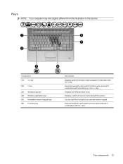
Keys
NOTE: Your computer may look slightly different from the illustration in this section.
Component (1) esc key
(2) fn key
(3) Windows logo key (4) Windows applications key (5) Embedded numeric keypad keys (6) Function keys
Description
Displays system information when pressed in combination with the fn key.
Executes frequently used system functions when pressed in combination with a function ...
Service Guide - Page 57
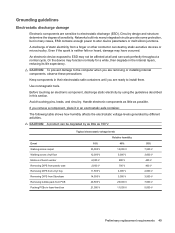
...determine the degree of sensitivity. Networks built into many integrated circuits provide some protection, but in many cases, ESD contains enough power to alter device parameters or melt silicon junctions....to the computer when you are removing or installing internal components, observe these precautions:
Keep components in their electrostatic-safe containers until you are ready to install them.
Use...
Service Guide - Page 66
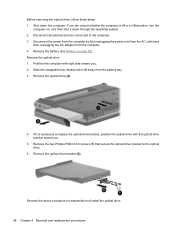
... down through the operating system. 2. Disconnect all external devices connected to the computer. 3. Disconnect the power from the computer by first unplugging the power cord from the AC outlet and
then unplugging the AC adapter from the computer. 4. Remove the battery (see Battery on page 55). Remove the optical drive: 1. Position the computer with right side toward you. 2. Slide the...
Service Guide - Page 69
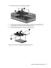
6. Remove the hard drive from the hard drive bay (4).
7. If it is necessary to replace the hard drive bracket, remove the four Phillips PM3.0×4.0 screws (1) that secure the hard drive bracket to the hard drive.
8. Lift the bracket (2) straight up to remove it from the hard drive.
Reverse this procedure to reassemble and install the hard drive.
Component replacement procedures 61
Service Guide - Page 72
... all external devices connected to the computer. 3. Disconnect the power from the computer by first unplugging the power cord from the AC outlet and
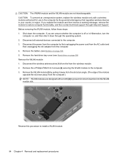
then unplugging the AC adapter from the computer. 4. Remove the battery (see Battery on page 55). 5. Remove the hard drive bay cover (see Hard drive on page 59) Remove the WLAN module: 1. Disconnect the wireless antenna...
Service Guide - Page 74
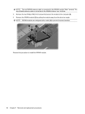
... The blue WWAN antenna cable is connected to the WWAN module "Aux" terminal. 5. Remove the two Phillips PM2.0×4.0 screws that secure the module to the computer (2). 6. Remove the WWAN... module (3) by pulling the module away from the slot at an angle. NOTE: WWAN modules are designed with a notch (4) to prevent incorrect insertion.
Reverse this procedure to install...
Service Guide - Page 76
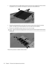
.... (The edge of the module opposite the slot rises away from the computer.)
5. Remove the module (2) by pulling it away from the slot at an angle. NOTE: Memory modules are designed with a notch to prevent incorrect insertion into the memory module slot.
Reverse this procedure to install a memory module.
68 Chapter 4 Removal and replacement procedures
Service Guide - Page 77
... the power cord from the AC outlet and
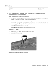
then unplugging the AC adapter from the computer. 4. Remove the battery (see Battery on page 55). 5. Remove the hard drive bay cover (see Hard drive on page 59). Remove the RTC battery: 1. Disconnect the RTC battery cable (1) from the system board. 2. Remove the RTC battery (2).
Reverse this procedure to install...
Service Guide - Page 79
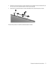
4. Release the camera/microphone module assembly from the display enclosure brackets (1), and lift it out as far as the camera/microphone module cable allows (2).
5. Disconnect the camera/microphone module cable (3) from the camera/microphone module. Reverse this procedure to install the camera/microphone module.
Component replacement procedures 71
Service Guide - Page 81
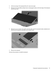
... disengage the tabs on the front edge of the keyboard
from the top cover.
7. Release the zero insertion force (ZIF) connector (1) to which the keyboard cable is attached and disconnect the keyboard cable (2) from the system board.
8. Remove the keyboard. Reverse this procedure to install the keyboard.
Component replacement procedures 73
Service Guide - Page 171
...), you may not have a recovery partition. Recovery discs have been included for computers that do not have a partition. Use these discs to recover your operating system and software. To check for the presence of a recovery partition, select Start > Computer. If the partition is present, an HP Recovery drive is listed in the Hard Disk Drives section of the window.
Backing up your information...
Service Guide - Page 172
...settings in a window, toolbar, or menu bar by taking a screen shot of your settings.
The screen shot can be a time-saver if you have to reset your preferences. To copy the screen and paste it into a word-processing document, follow these steps: a. Display the screen. b. Copy the screen:
To copy only the active window... your hard drive at a specific point in time. You can then recover back to that ...
Service Guide - Page 173
... BD-RE (rewritable Blu-ray) discs, are not compatible with the Recovery Manager software. ● The computer must be connected to AC power during this process. ● Only one set of recovery discs can be created per computer. ● Number each disc before inserting it into the computer optical drive. ● If necessary, you can exit the program before you...
Service Guide - Page 174
... creation, and then click Next. 4. Follow the on-screen instructions.
Performing a recovery
NOTE: You can recover only files that you have previously backed up. HP recommends that you use Recovery Manager to create an entire drive backup as soon as you set up your computer. Recovery Manager software allows you to repair or restore the system if you experience system...