Intel SC5400 driver and firmware


Related Intel SC5400 Manual Pages
Download the free PDF manual for Intel SC5400 and other Intel manuals at ManualOwl.com
User Manual - Page 7

..., upgrading, and repairing this server chassis. This document provides a brief overview of the features of the chassis, a list of accessories or other components you may need, troubleshooting information, and instructions on how to add and replace components on the Intel® Server Chassis SC5400. For the latest version of this manual, see http:// support.intel.com/support/motherboards/server...
User Manual - Page 9

...search "This Product."
For this information or software
For in-depth technical information about this product, including BIOS settings and chipset information If you just received this product and need to install it For virtual system tours and interactive repair information
Accessories or other Intel server products Hardware (peripheral boards, adapter cards) and operating systems that have been...
User Manual - Page 11

...
Component Identification 6 Internal Components 6 Front Control Panel 7 Intel® Local Control Panel 9 Back Panel Features 10 Peripheral Devices 11
Standard and Optional Hot-swap Drive Bays 12 Floppy / CD-ROM / DVD-ROM Slimline Carriers 12 Intel® Remote Management Module 13 Rack-mounted Systems 13
Chapter 2: Hardware Installations and Upgrades 15
Before You Begin ...15 Tools and...
User Manual - Page 30
... ambient temperature of 45C. The Intel® Server Chassis SC5400 does not support all SAS, SATA, or SCSI hard drives. See "Additional Information and Software" on page ix for an Internet link to a list of supported hardware.
Floppy / CD-ROM / DVD-ROM Slimline Carriers
For installation instructions on installing a floppy drive see "Installing and Removing a Slimline USB Floppy/CD/DVD Combo Kit...
User Manual - Page 33

2 Hardware Installations and
Upgrades
Before You Begin
Before working with your server product, pay close attention to the "Safety Information" on page iii. This document provides instructions for adding and replacing chassis components. For instructions on replacing components on the server board, such as the processor and memory DIMMs, see the instructions provided with the server board.
Tools ...
User Manual - Page 139

... and in particular, any costs relating to the removal or replacement of any product soldered or otherwise permanently affixed to any printed circuit board.
This Limited Warranty, and any implied warranties that may exist under state law, apply only to the original purchaser of the Product.
Intel® Server Chassis SC5400 User's Guide
83
Product Specification - Page 13

...-redundant power supply, which supports up to six hard drives. Two tachometer output fans are mounted in front of the server board. The optional 4-drive and 6-drive SAS (Serial Attach-SCSI)/SATA (Serial ATA) hot swap drive bay kits provide upgrades to allow support for 6 hot swap SAS/SATA drives. Three 5.25-inch half-height peripheral bays are available for installation of a floppy1, CD-ROM drive...
Product Specification - Page 14

... drive bay kits provide upgrades to allow support for up to 10 hot swap SAS/SATA drives. Three 5.25-inch half-height peripheral bays are available for installations of a floppy1, CD-ROM drive and/or other accessories. The standard chassis configuration is pedestal. A rack mount conversion kit is available.
Note:
1 The Intel® Server Board S5000PSL, Intel® Server Board S5000XSL and Intel...
Product Specification - Page 15

...Intel® Server Board S5000XSL
6-drive bay
4-drive bay optional accessory is available
Optional Hot Swap SAS/SATA
Drives
Power Supply and Required Power Cord Configuration
Hot Swap Fans
6-SAS/SATA Fixed 670WPFC Available as
6-SAS/SATA Requires one power an optional
Expander cord
accessory
4-SAS/SATA
4-SAS/SATA Expander
6-SAS/SATA One 830W PFC Available as
6-SAS/SATA module installed...
Product Specification - Page 28

.... ƒ In mirrored configuration, when memory-mirroring takes place and system loses memory redundancy. This is not covered by two. ƒ Redundancy loss such as power-supply or fan. This does not apply to non-redundant sub-systems. ƒ PCI-e* link errors ƒ CPU failure / disabled - if there are two processors and one of them fails ƒ...
Product Specification - Page 66

.../SATA HSBP contains a non-volatile 8Mbit Serial SPI FLASH Memory for Boot and Run-Time/Configuration code storage. The device resides on the SPI interface of VSC410* controller.
The Serial SPI Flash memory operates from the 3.3V rail.
6.1.4
LEDs
The 4HDD and 6HDD passive SAS/SATA HSBP contain a green STATUS LED and amber FAULT LED for each of the six hard disk drives...
Product Specification - Page 73

.../SATA hot swap drive cage can be connected to the SAS/SATA connectors on the server board or to a SAS/SATA RAID card, through the mated cable. The RAID level that is supported depends on the feature set of the SAS or SATA controller. The kit order codes are as follows:
ƒ AXX4DRV3G ƒ AXX6DRV3G
6.2 Intel® Server Chassis SC5400 4HDD and 6HDD Active SAS/SATA...
Product Specification - Page 75
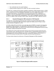
... Vitesse* Software Development Kit (SDK).
The v3000 CPU communicates with other devices in the enclosure through several two-wire serial interface ports, general purpose I/O, and LED drivers. It assembles enclosure status for transmission to the host controller through vendor-unique SMP frames or SSP frames for inband SCSI Enclosure Services (SES) or through a two-wire serial interface port.
The...
Product Specification - Page 79
... SC5400 5U Kit TPS
Hot Swap Hard Disk Drive Bays
6.2.3
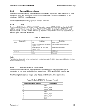
External Memory Device
The 4HDD and 6HDD active SAS/SATA HSBP contains a non-volatile 8Mbit Serial SPI FLASH Memory for Boot and Run-Time/Configuration code storage. The device resides on the SPI interface of VSC7161* SAS Expander.
The Serial SPI Flash memory operates from the 3.3V rail.
6.2.4
LEDs
The 4 and 6 HDD Active SAS/SATA...
Product Specification - Page 84

.... The kit includes a SAS/SATA hot-swap drive bay with mounting hardware.
With this kit, the SAS/SATA hot swap drive cage can be connected to the SAS/SATA connectors on the server board, or to a SAS/SATA RAID card, through the mated cable. The RAID level that is supported depends on the feature set of the SAS or SATA controller.
The kit order codes...
Product Specification - Page 91

... include fan control, drive insertion, drive removal, and drive failures. This interface is also used to update backplane firmware.
Figure 40. IPMB Cable
7.1.7
SES Cable for 6-Drive Bays (3-pin)
The SES cable is a private I2C bus between IO controller (HW or SW RAID) and backplane
used for enclosure management communication.
Figure 41. SES Cable
7.1.8
SGPIO Cable for 6-Drive Bays (4-pin...
Product Specification - Page 93

... hot-swap SAS/SATA hard disk drive bays, AXX6DRV3G and AXX4DRV3G, are available for all the Intel® Server Chassis SC5400 configurations. It is compatible with either SAS or SATA 3.5" hard drives. The kits include the following:
ƒ Drive rails ƒ Data cables ƒ Drive mounting bay ƒ IPMB cable ƒ SES cable ƒ SGPIO cable ƒ Common installation guide ƒ SATA/SAS...
Installation Guide - Page 1

Drive Cage Upgrade Kit Installation Guide: Intel® Server Chassis SC5400
Order Number: D38448-004
This document provides instructions for installing the following accessory kits: AXX4DRV3G AXX6DRV3G AXX4DRV3GEXP AXX6DRV3GEXP
Installation Guide - Page 5

...10 For a four-drive SAS hot swap drive cage installation 11 Six-drive Upgrade Drive Cage Installation 12 Make Backplane Cable Connections 14 For a six-drive SAS expander backplane installation 14 For a six-drive SAS/SATA backplane non-expander installation 15 Make Server Board/RAID Controller Card Connections 15 Reinstall Hot Swap Fans...16 Install Hot Swap Hard Drives 16 Install Fixed Hard...
Installation Guide - Page 10

Intel® Server Chassis SC5400 Installation
NOTE
This section only applies to drive cage upgrade kit installations in the Intel® Server Chassis SC5400, SC5400 BRP, or SC5400 LX.
Remove the Access Cover
When your chassis is upright (in a tower/pedestal position), and you are facing the front of it, the access cover ...