MSI PH61A driver and firmware

Related MSI PH61A Manual Pages
Download the free PDF manual for MSI PH61A and other MSI manuals at ManualOwl.com
User Guide - Page 2
... and no solution can be obtained from the user's manual, please contact your place of purchase or local distributor. Alternatively, please try the following help resources for further guidance.
◙ Visit the MSI website for technical guide, BIOS updates, driver updates, and
other information: http://www.msi.com/service/download
◙ Contact our technical staff at: http://support.msi.com
ii
User Guide - Page 4
... the user's authority to operate the equipment. Notice 2 Shielded interface cables and A.C. power cord, if any, must be used in order to comply with the emission limits.
VOIR LA NOTICE D'INSTALLATION AVANT DE RACCORDER AU RESEAU.
Micro-Star International MS-7732
This device complies with Part 15 of the FCC Rules. Operation is subject...
User Guide - Page 9
Preface
MS-7732 Appendix A Realtek Audio A-1
Installing the Realtek HD Audio Driver A-2 Software Configuration A-3 Hardware Default Setting A-5
ix
User Guide - Page 15
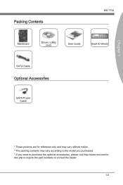
... Contents
MS-7732
Mainboard
Driver / Utility DVD
User Guide
Back IO Shield
SATA Cable
Optional Accessories
SATA Power Cable
* These pictures are for reference only and may vary without notice. * The packing contents may vary according to the model you purchased. * If you need to purchase the optional accessories, please visit http://www.msi.com/index.php to inquire...
User Guide - Page 17

... chapter provides you with the information about hardware setup procedures. While performing the installation, be careful in holding the components and following the installation procedures. For some components, if you install in the wrong orientation, the components will not work properly. Use a grounded wrist strap before handling computer components. Static electricity may damage the components...
User Guide - Page 19
Chapter 2
SATA3 SATA1 SATA4 SATA2
MS-7732
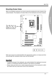
Mounting Screw Holes
When you install the mainboard, you have to place the mainboard into the chassis in the...has to toward the rear, the position for the I/O shield of the chassis.
Screw holes Refer above picture to install standoffs in the appropriate locations on chassis and then screw through the mainboard screw holes into the standoffs.
Important
&#...
User Guide - Page 20
Hardware Setup
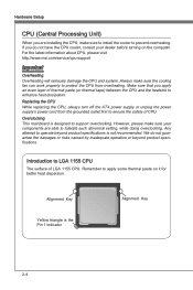
CPU (Central Processing Unit)
When you are installing the CPU, make sure to install the cooler to prevent overheating. If you do not have the CPU cooler, consult your dealer before turning on the computer. For the latest information about CPU, please visit http://www.msi.com/service/cpu-support
Important
Overheating Overheating will seriously damage the CPU and system. Always make...
User Guide - Page 21
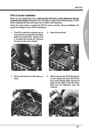
... protect the contact from damage. Before you install CPU, always cover it to protect the socket pin. Remove the cap (as the arrow shows).
2. Open the load level.
Chapter 2
3. Lift the load lever up to fully open position.
4. After confirming the CPU direction for correct mating, put down the CPU in the socket housing frame. Be...
User Guide - Page 22
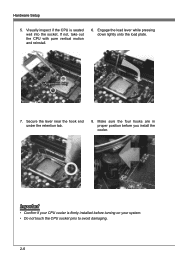
... and reinstall.
6. Engage the load lever while pressing down lightly onto the load plate.
Alignment Key
7. Secure the lever near the hook end under the retention tab.
8. Make sure the four hooks are in proper position before you install the cooler.
Important
• Confirm if your CPU cooler is firmly installed before turning on your...
User Guide - Page 23
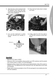
... mainboard to confirm that the clip-ends are correctly inserted.
12. Finally, attach the CPU Fan cable to the CPU fan connector on the mainboard.
Mainboard
Hook
Important
• Read the CPU status in BIOS. • Whenever CPU is not installed, always protect your CPU socket pin with the plastic
cap covered (shown in Figure 1) to avoid damaging...
User Guide - Page 24
Hardware Setup
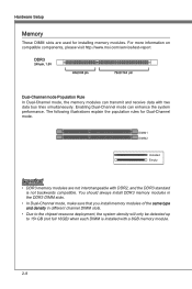
Memory
These DIMM slots are used for installing memory modules. For more information on compatible components, please visit http://www.msi.com/service/test-report
DDR3
240-pin, 1.5V
48x2=96 pin
72x2=144 pin
Dual-Channel mode Population Rule
In Dual-Channel mode, the memory modules can transmit and receive data with two data bus lines...
User Guide - Page 25
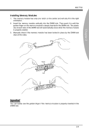
...Installing Memory Modules
1. The memory module has only one notch on the center and will only fit in the right orientation.
2. Insert the memory module vertically into the DIMM slot. Then push it in until the golden finger on the memory... of the DIMM slot will automatically close when the memory module is properly seated.
3. Manually check if the memory module has been locked in place by the DIMM ...
User Guide - Page 27
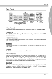
...you want to use a USB 3.0 device, you must use the USB 3.0 cable to connect to the USB 3.0 port.
▶ VGA Port The DB15-pin female connector is provided for monitor.
▶ DVI-D Port (optional) The DVI-D (Digital Visual Interface - Digital) connector allows you to connect a LCD monitor. It provides a high-speed digital interconnection between the computer and its display device. To connect an...
User Guide - Page 30
...
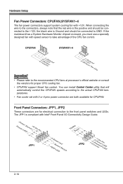
• Please refer to the recommended CPU fans at processor's official website or consult the vendors for proper CPU cooling fan.
• CPUFAN support Smart fan control. You can install Control Center utility that will automatically control the CPUFAN speeds according to the actual CPUFAN temperatures.
• Fan cooler set with 3 or 4 pins power connector are both available for CPUFAN...
User Guide - Page 36
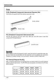
... Slot
PCIE x1 Slot
PCI (Peripheral Component Interconnect) Slot
The PCI slot supports LAN card, SCSI card, USB card, and other add-on cards that comply with PCI specifications.
32-bit PCI Slot
Important
When adding or removing expansion cards, make sure that you unplug the power supply first. Read the documentation for the expansion card to configure any necessary hardware or software settings...
User Guide - Page 38
..., the 1st line appearing after the memory count is the BIOS version. It is usually in the format: E7732IMS.xxx 022811 where: 1st digit refers to BIOS type as E = EFI 2nd - 5th digit refers to the model number. 6th digit refers to the chipset as I = Intel, N = nVidia, A = AMD and V = VIA. 7th - 8th digit refers to the customer as MS...
User Guide - Page 41
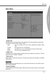
... time). The time format is .
▶ SATA Port1~6
Press to enter the sub-menu. The sub-menu shows the information of installed SATA device.
Important
SATA Port1~6 are appearing when you connect the HD devices to the SATA connectors on the mainboard.
▶ System Information This area shows the CPU information, BIOS version and memory status of your system (read only).
3-5
User Guide - Page 44
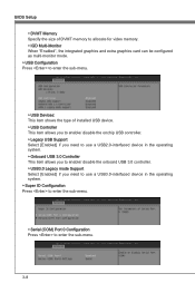
... to use a USB2.0-interfaced device in the operating system. ▶ Onboard USB 3.0 Controller This item allows you to enable/ disable the onboard USB 3.0 controller. ▶ USB3.0 Legacy mode Support Select [Enabled] if you need to use a USB3.0-interfaced device in the operating system. ▶ Super IO Configuration Press to enter the sub-menu.
▶ Serial (COM) Port 0 Configuration Press...
User Guide - Page 58
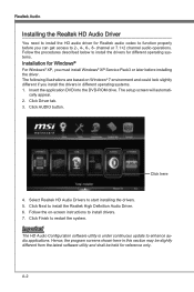
.... 1. Insert the application DVD into the DVD-ROM drive. The setup screen will automati-
cally appear. 2. Click Driver tab. 3. Click AUDIO button.
Click here
4. Select Realtek HD Audio Drivers to start installing the drivers. 5. Click Next to install the Realtek High Definition Audio Driver. 6. Follow the on-screen instructions to install drivers. 7. Click Finish to restart the system.
Important...
User Guide - Page 59
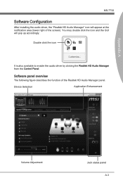
... installing the audio driver, the "Realtek HD Audio Manager" icon will appear at the notification area (lower right of the screen). You may double click the icon and the GUI will pop up accordingly.
Double click the icon
It is also available to enable the audio driver by clicking the Realtek HD Audio Manager from the Control Panel.
Software...