Sony FWD-32LX1 driver and firmware
Related Sony FWD-32LX1 Manual Pages
Download the free PDF manual for Sony FWD-32LX1 and other Sony manuals at ManualOwl.com
Child Safety: It Makes A Difference How and Where You Use Your Flat Panel Display - Page 1

.... Follow the manufacturer's recommendations for the safe installation and use of your flat panel display.
• Carefully read and understand all enclosed instructions for proper use of this product.
• Don't allow children to climb on or play with furniture and television sets. • Don't place flat panel displays on furniture that can easily be used...
Mounting Bracket Instruction Manual - Page 1
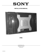
INSTALLATION MANUAL
IN-SFM2.R1
SFM2
Sony Electronics, Inc.
16540 West Bernardo Drive San Diego, CA 92127 www.sony.com
Mounting Bracket Instruction Manual - Page 2
... TOOLS ...- 4 INSTALLATION PROCEDURES ...- 5 SINGLE STUD INSTALLATION ...- 5 SOLID STRUCTURE INSTALLATION ...- 6 ATTACHING THE ADAPTER PLATE AND THE BACKPLATE COVER 7 ATTACHING THE ADAPTER PLATE /BACKPLATE COVER TO THE DISPLAY 9 ATTACHING THE DISPLAY TO THE BACKPLATE 10 TECHNICAL SPECIFICATIONS ...- 11 WARRANTY ...- 12 CUSTOMER SUPPORT ...- 12 NOTES ...- 12 -
Page - 2 -
Installation Manual
Mounting Bracket Instruction Manual - Page 3
... PERSONAL INJURY AND PROPERTY DAMAGE. KEEP THESE INSTALLATION INSTRUCTIONS IN AN EASILY ACCESSIBLE LOCATION FOR FUTURE REFERENCE.
Indicates that the power plug is to be disconnected from the power outlet.
Safety precautions must be taken at all times.
Warning and Caution statements.
Contact Sony Electronics with any questions.
Do not install on a structure that is prone to...
Mounting Bracket Instruction Manual - Page 4
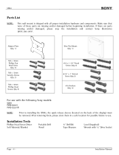
... (Qty 4)
For use with the following Sony models:
SONY FWD-32LX1 FWD-32LX1R
NOTE:
Prior to installing the SFM2, the quick release sleeves (located on the back of the display) must be removed. After removing them, please store them in a safe location for possible future re-use.
Installation Tools
Phillips Head Screw Driver Soft Material/ Blanket
Portable Drill Pencil...
Mounting Bracket Instruction Manual - Page 5
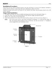
... 5). If any of the hardware described is missing, do not continue. Contact Sony Electronics immediately at (877) 350-3477. Separate the plates and choose the location for the monitor and follow any precautions listed in the LCD owners' manual.
Single Stud Installation
1. For single wood studs, use the two middle mounting points found...
Mounting Bracket Instruction Manual - Page 6
SFM2
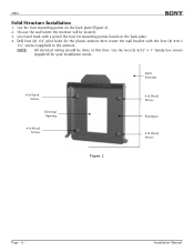
Solid Structure Installation
1. Use the four mounting points on the back plate (Figure 2). 2. Choose the wall where the monitor will be ... electrical wiring should be done at this time. Use the two (2) 6/32" x 1" handy box screws
(supplied) for your installation needs.
#10 Wood Screws
Electrical Opening
#10 Wood Screws
Solid Structure
#10 Wood Screws
Frontplate
#10 Wood Screws
Figure 2
Page...
Mounting Bracket Instruction Manual - Page 7
...Backplate Cover
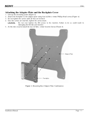
1. Line up the mounting points (Figure 3). 2. Attach the frontplate to the adapter plate using four (4) M4 x 10mm Phillips Head screws (Figure 4). 3. Do not tighten ... the threads and monitor.
5. At this time, loosely install the two (2) M6 x 12mm Security Screws (Figure 4).
Adapter Plate
Frontplate
Figure 3. Mounting Box/ Adapter Plate Combination
Installation Manual
Page - 7 -
Mounting Bracket Instruction Manual - Page 8
SFM2
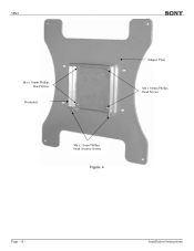
M4 x 10mm Phillips Head Screws
Frontplate
Adapter Plate
M4 x 10mm Phillips Head Screws
M6 x 12mm Phillips Head Security Screws
Figure 4
Page - 8 -
Installation Instructions
Mounting Bracket Instruction Manual - Page 9
... Display
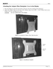
1. Place the display on a flat and soft surface and locate the four mounting points (Figure 5). 2. Attach the Adapter Plate to the back of the display using four (4) M6 x 10mm Phillips Head screws
(Figure 6). Do not overtighten the screws. CAUTION: DO NOT OVERTIGHTEN THE SCREWS.
Figure 5. Installing the Adapter Plate/ Mounting Box
Adapter Plate Ultra Flat Mount
Installation Instructions...
Mounting Bracket Instruction Manual - Page 10
... the Backplate
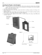
NOTE: For clarity purposes, the following illustrations will be shown without the adapter plate and display attached. This must be done to show how the positioning of the backplate cover and the... 9).
Flange Opening (Slot opening on top of frontplate)
Flange
Frontplate
Backplate
Figure 7
Figure 8
Page - 10 -
Simulated Display
M6 x 12mm Security Screws
Figure 9
Installation Manual
Mounting Bracket Instruction Manual - Page 12
..., adapters, display equipment or personal injury.
Customer Support
In the event of missing and/or damaged equipment, or technical questions, the following information can help in the completion of the installation. Customer Service 877-350-3477
Notes
©Sony 2005
Page - 12 -
Sony Electronics, Inc.
16540 West Bernardo Drive San Diego, CA 92127 (800) 350-3477 www.sony.com
Installation Manual
Operating Instructions (Flat Panel Display) - Page 2
...
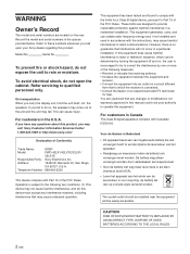
If you have any questions about this product, you may call; Sony Customer Information Services Center 1-800-222-7669 or http://www.sony.com/
Declaration of Conformity
Trade Name:
SONY
Model:
FWD-42LX1/42LX1E/32LX1/
32LX1E
Responsible Party: Sony Electronics Inc.
Address:
16450 W. Bernardo Dr, San Diego,
CA 92127 U.S.A.
Telephone Number: 858-942-2230
This device complies with Part 15...
Operating Instructions (Flat Panel Display) - Page 5
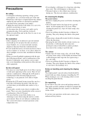
... Take this into account when you install the unit outdoor or by a window. • Do not push, scratch...cleaning the display The panel surface • Be sure to unplug the power cord before cleaning the
display. &#...display panel The display panel's special surface finish should be treated with care when cleaning or handling the TV...questions on this unit, contact your authorized Sony dealers.
5 (GB)
Operating Instructions (Flat Panel Display) - Page 7
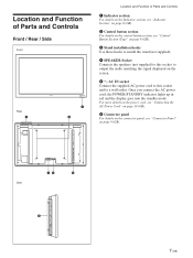
... details on the control button section, see "Control Button Section (Top)" on page 8 (GB).
3 Stand installation hooks Use these hooks to install the stand (not supplied).
4 SPEAKER Socket Connects the speakers (not supplied) to this socket to output the audio matching the signal displayed on the screen.
5 - AC IN socket Connect the supplied AC power cord to...
Operating Instructions (Flat Panel Display) - Page 8
... and Controls
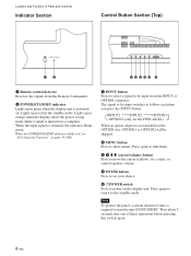
Indicator Section
Control Button Section (Top)
12
12345 6
1 Remote control detector Receives the signals from the Remote Commander.
2 POWER/STANDBY indicator Lights up in green when the display unit is powered on. Lights up in red in the standby mode. Lights up in orange when the display enters the power saving mode while a signal is input from a computer. When...
Operating Instructions (Flat Panel Display) - Page 10
... of a computer.
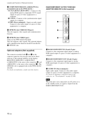
AUDIO (Stereo minijack) : Inputs an audio signal. Connects to the audio output of a piece of video equipment or a computer.
8 OPTION1 slot (VIDEO/COM port) This slot supports video signals and communication function.
9 OPTION2 slot (VIDEO port) (Only for the FWD-42LX1/42LX1E) This slot supports video signals. The optional adaptor with communication function should be installed in...
Operating Instructions (Flat Panel Display) - Page 11
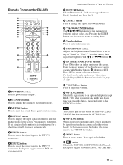
Remote Commander RM-980
1
2
MUTING DISPLAY STBY ON
3
4
5
qf
6
qg
7
qh
8
qj
9
ENTER
123
0
456
789
qa
0
qk
qs
ON SET
qd
ql
MONITOR
RM-980
1 POWER ON switch Press to power on the display.
2 STANDBY button Press to change the display to the standby mode.
3 MUTING button Press to mute the sound. Press again to restore sound...
Operating Instructions (Flat Panel Display) - Page 12
Location and Function of Parts and Controls
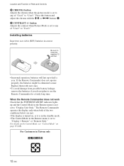
qk CHROMA button Adjusts the chroma when the picture mode is set to any of "User1" to "User3." Press this button and adjust the chroma with the M/m or
Pro Displays Brochure - Page 9
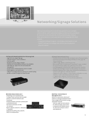
... software/playlist control included • Dolby digital 5.1 surround sound • USB port for storage expansion and ease of content loading • 60GB local media storage (ICS-FW40D model)
EBS-N200D Network Media Player • Transmit, receive, and control video and audio over an IP network display • Real Time streaming and decoding of MPEG/4/2/1 files, jpgs and
internet...