Biostar I945G-M7 driver and firmware
Related Biostar I945G-M7 Manual Pages
Download the free PDF manual for Biostar I945G-M7 and other Biostar manuals at ManualOwl.com
Setup Manual - Page 1

...digital devic e, purs uant to Part 15 of the FCC Rules .T hese limits are designed to provide reasonable protec tion against harmful interference in a residential installation. T his equipment generates , uses and can radiate radio frequency energy and, if not ins talled and used in accordance with the instructions...writing.
The content of this user's manual is subject to be c hanged without notice and ...
Setup Manual - Page 2

... Checklist 4
1.3
Layout and Components 5
Chapter 2: Hardware Installation 6
2.1
Installing Central Processing Unit (CPU 6
2.2
FAN Headers 8
2.3
Installing System Memory 9
2.4
Connectors and Slots 10
Chapter 3: Headers & Jumpers Setup 12
3.1
How to Setup Jumpers 12
3.2
Detail Settings 12
Chapter 4: Useful Help 18
4.1
Award BIOS Beep Code 18
4.2
Extra Information 18...
Setup Manual - Page 3

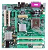
945G-M7 / 945P-M7
CHAPTER 1: INTRODUCTION
1.1 MOTHERBOARD FEATURES
C PU Supports LGA 775. Supports Intel Pentium 4 processor up to 3.8GHz. Supports Intel Pentium D processor. Front Side Bus at the following frequency ranges: 533MHz (133MHz Core Clock) 800MHz (200MHz Core Clock) 1066MHz (266MHz Core Clock) Supports Hyper-Threading Technology. (HT) Supports Execute Disable Bit ...
Setup Manual - Page 6

...in connector.
P S/2 Mouse
P rinter port
Gi ga LAN / LAN
P S/2 Key board
C OM1 COM1
V GA 1 (only for 945G-M7)
USB x2
USB x 2
1.2 PACKAGE CHECKLIST
FDD Cable X 1 HDD Cable X 1 User's Manual X 1 Serial ATA Cable X 1 Fully Setup Driver CD X 1 Rear I/O Panel for AT X Case X 1 USB 2.0 Cable X1 (optional) S/PDIF Cable X 1 (optional) Serial ATA Power Switch Cable X 1 (optional)
Line In/ Surround...
Setup Manual - Page 8

945G-M7 / 945P-M7
CHAPTER 2: HARDWARE INSTALLATION
2.1 INSTALLING CENTRAL PROCESSING UNIT (CPU)
Special Notice: Remove Pin Cap before installation, and make good preservation for future use. When the CPU is removed, cover the Pin Cap on the empty socket to ensure pin legs won't be damaged.
Pin Cap
Step 1: Pull the socket locking lever ...
Setup Manual - Page 9

... cut edge. The CPU will fit only in the correct orientation. Step 2-1:
Step 2-2:
Step 3: Hold the CPU down firmly, and then lower the lever to locked position to complete the installation.
Step 4: Put the CPU Fan and heatsink assembly on the CPU and buckle it on the retention frame. Connect the CPU FAN power cable into the JCFAN1...
Setup Manual - Page 11

DD R2_A1 D DR 2_A2 DD R2_B1 D DR 2_B2
945G-M7 / 945P-M7 2.3 INSTALLING SYSTEM MEMORY
1. Unlock a DIMM slot by pressing the retaining clips outward. Align a DIMM on the slot such that the notch on the DIMM matches the break on the Slot.
2. Insert the DIMM vertically and firmly into the slot until the retaining chip snap back in place and the DIMM is properly seated.
9
Setup Manual - Page 20

....biostar.com.tw 3. Confirm motherboard model and download the respectively BIOS from Biostar website. 4. Copy "AWDFLASH.exe" and respectively BIOS into floppy disk. 5. Insert the bootable disk into floppy drive and press Enter. 6. System will boo-up to DOS prompt. 7. Type "Awdflash xxxx.bf/sn/py/r" in DOS prompt. 8. System will update BIOS automatically and restart. 9. The BIOS has been recovered...
Setup Manual - Page 22

... into place.
System does not boot from hard disk 1. driv e, can be booted f rom optical driv e.
2.
Check cable running from disk to disk controller board. Make sure both ends are securely plugged in; check the driv e type in the standard CMOS setup. Backing up the hard drive is extremely important. All hard disks are capable of breaking down at any time...
Setup Manual - Page 23

.... Also, in the About panel, you can get detail descriptions about BIOS model and chipsets. In addition, the frequency status of CPU, memory, AGP and PCI along with the CPU speed are synchronically shown on our main panel. Moreover, to protect users' computer systems if the setting is not appropriate when testing and results in system fail or...
Setup Manual - Page 24

945G-M7 / 945P-M7 5.3 INSTALLATION
1. Execute the setup execution file, and then the following dialog will pop up. Please click "Next" button and follow the default procedure to i n stall .
2. When you see the following dialog in setup procedure, it means setup is completed. ... are just only for reference, the screen printed in this user manual will change according to your motherboard on hand.
22
Setup Manual - Page 25

945G-M7 / 945P-M7 5.4 [WARPSPEEDER™] INCLUDES 1 TRAY ICON AND 5 PANELS
1. Tray Icon: Whenever the Tray Icon utility is launched, it will display a little tray icon on the right side of Windows Taskbar.
This utility is responsible for conveniently invoking [WarpSpeeder™] Utility. You can use the mouse by clicking the left button in order...
Setup Manual - Page 26

945G-M7 / 945P-M7 2. Main Panel
If you click the tray icon, [WarpSpeeder™] utility will be invoked. Please refer to the following figure; the utility's first window you will see is Main Panel. Main Panel contains fe ature s as follows: a. Display the CPU Speed, CPU external clock, Memory clock, AGP clock, and PCI clock information. b. Contains About, Voltage...
Setup Manual - Page 33

... it retains the Setup information when the power is turned off.
The Award BIOS™ installed in your computer system's ROM (Read Only Memory) is a custom version of an industry standard BIOS. This means that it supports Intel Pentium ® 4 processor input/output system. The BIOS provides critical low-level support for standard devices such as disk drives and serial and parallel ports.
Adding...
Setup Manual - Page 35

... Menu allows you to select from several setup functions. Use the arrow keys to select among the items and press to accept and enter the sub-menu.
!! WARNING !! The information about BIOS defaults on manual (Figure 1,2,3,4,5,6,7,8,9) is just for reference, please refer to the BIOS installed on board, for update information.
Figure 1. Main Menu
Standard CMOS Features...
Setup Manual - Page 37

945G-M7 & 945P-M7 BIOS SETUP
Set User Password If the Supervisor Password is not set, then the User Password will function in the same way as the Supervisor Password. If the Supervisor Password is set and the User Password is set, the "User" will only be able to view configurations but will not be able to change them.
Save & Exit Setup
Save all configuration changes...
Setup Manual - Page 39

945G-M7 & 945P-M7 BIOS SETUP
Main Menu Selections This table shows the selections that you can make on the Main Menu.
Item Date
Time IDE Primary Master IDE Primary Slave IDE Secondary Master IDE Secondary Slave
Drive A Drive B
Video
Options mm : dd : yy
hh ... enter the sub menu of detailed options. Select the type of floppy disk drive installed in your system.
Select the default video device.
7
Setup Manual - Page 44

945G-M7 & 945P-M7 BIOS SETUP
Boot Seq & Floppy Setup This item allows you to setup Boot Seq & Floppy.
Hard Disk Boot Priority These BIOS attempt to arrange the Hard Disk boot sequence automatically. This will depend on which Hard Disk is installed.
The Choices: Pri. Master, Pri.Slave, Sec.Master, Sec.Slave, USBHDD0, USBHDD1, USBHDD2 and Bootable Add-in Cards.
12
Setup Manual - Page 45

945G-M7 & 945P-M7 BIOS SETUP
First/Second/Third/Boot Other Device These BIOS attempt to load the operating system from the device in the sequence selected in these items. The Choices: Floppy, LS120, HDD-0, SCSI, CDROM, ZIP100, LAN, Disabled.
Swap Floppy Drive For systems with two floppy drives, this option allows you to swap logical drive assignments. The Choices: Disabled (default), Enabled.
...
Setup Manual - Page 53

... if it is supported by the IDE hard drives in your system. As well, your operating environment requires a DMA driver (Windows 95 OSR2 or a third party IDE bus master driver). If your hard drive and your system software both support Ultra DMA/100, select Auto to enable BIOS support. The Choices: Auto (default), Disabled.
SATA Mode The Choices: IDE (default), RAID, AHCI.
21