Lexmark Z31 Color Jetprinter driver and firmware
Drivers and firmware downloads for this Lexmark item

Related Lexmark Z31 Color Jetprinter Manual Pages
Download the free PDF manual for Lexmark Z31 Color Jetprinter and other Lexmark manuals at ManualOwl.com
Service Manual - Page 2

....
Color Jetprinter is a trademark of Lexmark International, Inc.
Other trademarks are the property of their respective owners.
© Copyright Lexmark International, Inc. 1999. All rights reserved.
UNITED STATES GOVERNMENT RESTRICTED RIGHTS This software and documentation are provided with RESTRICTED RIGHTS. Use, duplication or disclosure by the Government is subject to restrictions as set forth...
Service Manual - Page 5

... manual describes the Lexmark Z31 Color Jetprinter™(4099) and is divided into the following chapters:
1. General Information contains a general description of the printer and the maintenance approach used to repair it. Special tools and test equipment are listed in this chapter, as well as general environmental and safety instructions.
2. Diagnostic Information contains an error indicator...
Service Manual - Page 11

...General Information
The Lexmark Z31 Color Jetprinter (4099) is a personal, near laserquality inkjet printer. The printer contains single-unit customer replaceable supply items. Dual printheads provide color and true black printing without changing printheads. The black cartridge has a total of 208 nozzles and installs on the right. The color cartridge has a total of 192 nozzles and installs on the...
Service Manual - Page 19

...:
• An open or short in the motor. • An open or short in the motor driver
on the system board.
• A bind in the carrier transport
mechanism.
With the carrier transport motor cable disconnected from the system board, check for 0 to 10 ohms between the following pins on the motor:
J8-1 and J8...
Service Manual - Page 23

... An open or short in the motor driver on the
system board • A bind in the paper feed mechanism With the paper feed motor cable disconnected from the system board, check for approximately 10 ohms between the...turns in one direction only, replace the system board.
Binds in the paper feed motor or gear train can cause intermittent false paper jam errors. Remove the paper feed motor and check the...
Service Manual - Page 24

...Examine the machine for the following before you begin this service check:
• Check the entire paper path for obstructions. • Be sure the correct type of paper is being used. • Be sure the printer is installed on a flat surface.
FRU
Action
1 Large and Small... for wear:
5 End-of-Forms Flag
• Exit roller • Star rollers
Check for binds or damage.
2-10 Service Manual
Service Manual - Page 29

...Install paper in the sheet feeder. 6. Turn the printer off. 7. Hold down the Paper Feed and Power buttons at the same time until both lights begin to flash. 8. Release both buttons. Test pages print until the Power button is pressed. The printer prints four lines of black and color... not working. If a print quality problem exists, see "Print Quality Service Check" on page 2-12.
Diagnostic Aids 3-1
Service Manual - Page 31
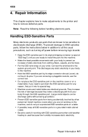
... to make adjustments to the printer and how to remove defective ... ESD-sensitive parts, follow the instructions below in addition to all the usual precautions, such as turning off power before removing logic boards:
• Keep the ESD-...
• Prevent ESD-sensitive parts from being accidentally touched by other
personnel. Install machine covers when you are not working on the machine, and do not ...
Service Manual - Page 35

...assembly. 4. Disconnect the printhead carrier cables from the system board. 5. Remove the retainers from the ends of the carrier guide rod. 6. Slide the carrier guide rod out the right side of ...cable through the hole in the carrier frame. When reinstalling the cable retainer, ensure the two retainer tabs are through the carrier frame before latching the two retainer latches. Note: Before installing...
Service Manual - Page 37
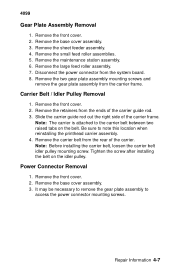
...feed roller assembly. 7. Disconnect the power connector from the system board. 8. Remove the two gear ...guide rod out the right side of the carrier frame.
Note: The carrier is attached to the carrier belt between two raised tabs on the belt. Be sure to note this location when reinstalling the printhead carrier assembly. 4. Remove the carrier belt from the rear of the carrier. Note: Before installing...