ASRock H410TM-ITX driver and firmware
Related ASRock H410TM-ITX Manual Pages
Download the free PDF manual for ASRock H410TM-ITX and other ASRock manuals at ManualOwl.com
User Manual - Page 4
...
1
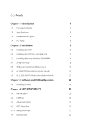
1.2 Specifications
2
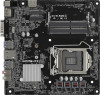
1.3 Motherboard Layout
6
1.4 I/O Panel
8
Chapter 2 Installation
9
2.1 Installing the CPU
10
2.2 Installing the CPU Fan and Heatsink
13
2.3 Installing Memory Modules (SO-DIMM)
14
2.4 Jumpers Setup
15
2.5 Onboard Headers and Connectors
17
2.6 M.2 WiFi/BT Module Installation Guide
21
2.7 M.2_SSD (NGFF) Module Installation Guide
23
Chapter 3 Software and...
User Manual - Page 6
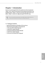
... and the BIOS software might be updated, the content of this documentation will be subject to change without notice.
1.1 Package Contents
• H410TM-ITX Motherboard (Thin Mini-ITX Form Factor) • H410TM-ITX Quick Installation Guide (Optional) • 1 x Thin-Mini ITX I/O Shield (Optional) • 1 x Mini ITX I/O Shield (Optional) • 2 x Serial ATA (SATA) Data Cables (Optional...
User Manual - Page 7
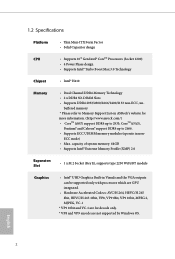
... Gen Intel® CoreTM Processors (Socket 1200) • 4 Power Phase design • Supports Intel® Turbo Boost Max 3.0 Technology
Chipset
• Intel® H410
Memory
• Dual Channel DDR4 Memory Technology • 2 x DDR4 SO-DIMM Slots • Supports DDR4 2933/2800/2666/2400/2133 non-ECC, un-
buffered memory * Please refer to Memory Support List on ASRock's website for more...
User Manual - Page 9
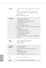
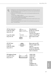
... The CPU Fan Connectors support the CPU fan of maximum 1A (12W) fan power. • 1 x 4 pin 19V Power Connector • 1 x Thermal Sensor Header (2-Pin) • 1 x Front Panel Audio Connector • 1 x Internal Speaker Header (4-Pin) • 2 x SATA Power Connectors • 2 x USB 2.0 Headers (Support 4 USB 2.0 ports) (Supports ESD
Protection)
BIOS Feature
• AMI UEFI Legal BIOS with...
User Manual - Page 14
H410TM-ITX
Chapter 2 Installation
This is a Thin Mini-ITX form factor motherboard. Before you install the motherboard, study the configuration of your chassis to ensure that the motherboard fits into it.
Pre-installation Precautions
Take note of the following precautions before you install motherboard components or change any motherboard settings. • Make sure to unplug the power cord before ...
User Manual - Page 15
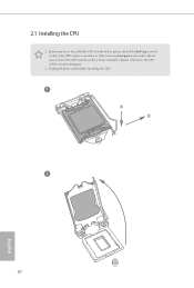
2.1 Installing the CPU
1. Before you insert the 1200-Pin CPU into the socket, please check if the PnP cap is on the socket, if the CPU surface is unclean, or if there are any bent pins in the socket. Do not force to insert the CPU into the socket if above situation is found. Otherwise, the CPU will be seriously damaged.
2. Unplug all power cables before installing the CPU.
1 A B
2
10
English
User Manual - Page 18
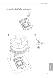
2.2 Installing the CPU Fan and Heatsink
H410TM-ITX
1
2
CPU_FAN
13
English
User Manual - Page 19
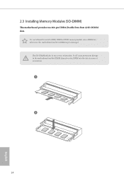
... Rate 4) SO-DIMM slots.
It is not allowed to install a DDR, DDR2 or DDR3 memory module into a DDR4 slot; otherwise, this motherboard and SO-DIMM may be damaged.
The SO-DIMM only fits in one correct orientation. It will cause permanent damage to the motherboard and the DIMM if you force the DIMM into...
User Manual - Page 20
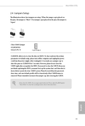
... reset the system parameters to default setup, please turn off the computer and unplug the power cord from the power supply. After waiting for 15 seconds, use a jumper cap to short the pins on CLRMOS1 for 5 seconds. However, please do not clear the CMOS right after you update the BIOS. If you need to clear the...
User Manual - Page 24
H410TM-ITX
1. High Definition Audio supports Jack Sensing, but the panel wire on the chassis must support HDA to function correctly. Please follow the instructions in our manual and chassis manual to install your system.
2. If you use an AC'97 audio panel, please install it to the front panel audio header by the steps below: A. Connect Mic_IN (MIC) to MIC2_L. B. Connect Audio_R...
User Manual - Page 26
H410TM-ITX
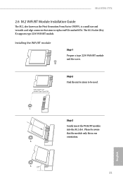
2.6 M.2 WiFi/BT Module Installation Guide
The M.2, also known as the Next Generation Form Factor (NGFF), is a small size and versatile card edge connector that aims to replace mPCIe and mSATA. The M.2 Socket (Key E) supports type 2230 WiFi/BT module.
Installing the WiFi/BT module
Step 1
Prepare a type 2230 WiFi/BT module and the screw.
PCB Length: 3cm Module Type: Type2230...
User Manual - Page 28
H410TM-ITX
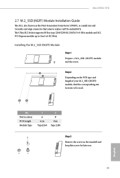
2.7 M.2_SSD (NGFF) Module Installation Guide
The M.2, also known as the Next Generation Form Factor (NGFF), is a small size and versatile card edge connector that aims to replace mPCIe and mSATA. The Ultra M.2 Socket supports M Key type 2260/2280 M.2 SATA3 6.0 Gb/s module and M.2 PCI Express module up to Gen3 x4 (32 Gb/s).
Installing the M.2_SSD (NGFF) Module
Step...
User Manual - Page 33
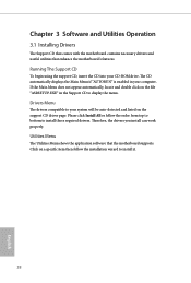
Chapter 3 Software and Utilities Operation
3.1 Installing Drivers
The Support CD that comes with the motherboard contains necessary drivers and useful utilities that enhance the motherboard's features.
Running The Support CD
To begin using the support CD, insert the CD into your CD-ROM drive. The CD automatically displays the Main Menu if "AUTORUN" is enabled in your computer. If the Main Menu ...
User Manual - Page 34
H410TM-ITX
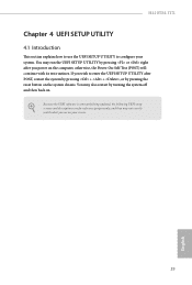
Chapter 4 UEFI SETUP UTILITY
4.1 Introduction
This section explains how to use the UEFI SETUP UTILITY to configure your system. You may run the UEFI SETUP UTILITY by pressing or right after you power on the computer, otherwise, the Power-On-Self-Test (POST) will continue with its test routines. If you wish to enter the UEFI SETUP UTILITY...
User Manual - Page 39
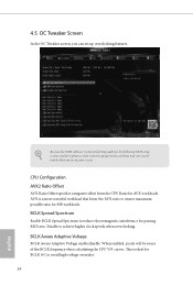
...set up overclocking features.
Because the UEFI software is constantly being updated, the following UEFI setup screens and descriptions are for reference purpose only, and they may not exactly match what you see on your screen.
CPU....
BCLK Aware Adaptive Voltage
BCLK Aware Adaptive Voltage enable/disable. When enabled, pcode will be aware of the BCLK frequency when calculating the CPU V/F curves. ...
User Manual - Page 42
H410TM-ITX
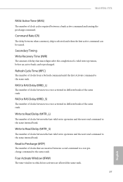
RAS# Active Time (tRAS)
The number of clock cycles required between a bank active command and issuing the precharge command.
Command Rate (CR)
The delay between when a memory chip is selected and when the first active command can be issued.
Secondary Timing Write Recovery...same rank.
Four Activate Window (tFAW)
The time window in which four activates are allowed the same rank.
37
English
User Manual - Page 48
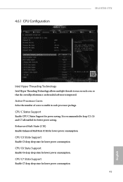
4.6.1 CPU Configuration
H410TM-ITX
Intel Hyper Threading Technology
Intel Hyper Threading Technology allows multiple threads to run on each core, so that the overall performance on threaded software is improved.
Active Processor Cores
Select the number of cores to enable in each processor package.
CPU C States Support
Enable CPU C States Support for power saving. It is recommended to keep C3, C6...
User Manual - Page 55
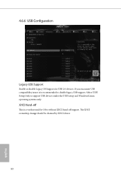
... Support
Enable or disable Legacy OS Support for USB 2.0 devices. If you encounter USB compatibility issues it is recommended to disable legacy USB support. Select UEFI Setup Only to support USB devices under the UEFI setup and Windows/Linux operating systems only.
XHCI Hand-off
This is a workaround for OSes without XHCI hand-off support. The XHCI ownership change should be claimed by XHCI driver...
User Manual - Page 58
...H410TM-ITX
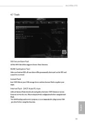
SSD Secure Erase Tool
All the SSD's listed that supports Secure Erase function.
NVME Sanitization Tool
After you Sanitize SSD, all user data will be permanently destroyed on the SSD and cannot be recovered.
Instant Flash
Save UEFI files in your USB storage device and run Instant Flash to update your UEFI.
Internet Flash - DHCP (Auto IP), Auto
ASRock Internet Flash downloads and updates...
User Manual - Page 59
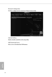
Network Configuration
Use this to configure internet connection settings for Internet Flash.
Internet Setting
Enable or disable sound effects in the setup utility.
UEFI Download Server
Select a server to download the UEFI firmware.
54
English