ASRock H61M-XT PLUS driver and firmware
Related ASRock H61M-XT PLUS Manual Pages
Download the free PDF manual for ASRock H61M-XT PLUS and other ASRock manuals at ManualOwl.com
User Manual - Page 3
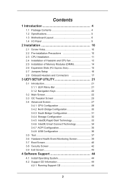
...1 Introduction 4
1.1 Package Contents 4 1.2 Speciications 5 1.3 Motherboard Layout 8 1.4 I/O Panel 9
2 Installation 10
2.1 Screw Holes 10 2.2 Pre-installation Precautions 10 2.3 CPU Installation 11 2.4 Installation of Heatsink and CPU fan 13 2.5 Installation of Memory Modules (DIMM 14 2.6 Expansion Slots (PCI Express Slots 15 2.7 Jumpers Setup 16 2.8 Onboard Headers and Connectors 17...
User Manual - Page 5
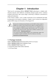
.... ASRock website http://www.asrock.com If you require technical support related to this motherboard, please visit our website for speciic information about the model you are using. www.asrock.com/support/index.asp
1.1 Package Contents
ASRock H61M-XT PLUS Motherboard (Micro ATX Form Factor) ASRock H61M-XT PLUS Quick Installation Guide ASRock H61M-XT PLUS Support CD 2 x Serial ATA (SATA) Data Cables...
User Manual - Page 8
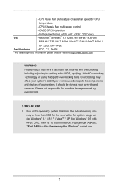
... caused by overclocking.
CAUTION!
1. Due to the operating system limitation, the actual memory size may be less than 4GB for the reservation for system usage under Windows® 8.1 / 8 / 7 / VistaTM / XP. For Windows® OS with 64-bit CPU, there is no such limitation. You can use ASRock XFast RAM to utilize the memory that Windows® cannot use.
7
User Manual - Page 10
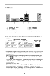
... Activity Orange 100Mbps connection
On
Link
Green 1Gbps connection
LAN Port
** To enable Multi-Streaming function, you need to connect a front panel audio cable to the front
panel audio header. Please refer to below steps for the software setting of Multi-Streaming.
For Windows® XP:
After restarting your computer, you will ind "Mixer" tool on your system. Please...
User Manual - Page 11
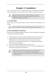
... screws into the holes indicated by circles to secure the motherboard to the chassis.
Do not over-tighten the screws! Doing so may damage the motherboard.
2.2 Pre-installation Precautions
Take note of the following precautions before you install motherboard components or change any motherboard settings.
1. Unplug the power cord from the wall socket before touching any component. 2. To...
User Manual - Page 12
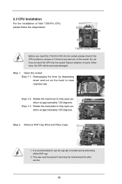
2.3 CPU Installation
For the installation of Intel 1155-Pin CPU, please follow the steps below.
Load Plate
Load Lever
Contact Array
Socket Body
1155-Pin Socket Overview
Before you insert the 1155-Pin CPU into the socket, please check if the CPU surface is unclean or if there is any bent pin on the socket. Do not force to...
User Manual - Page 14
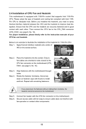
... refer to the instruction manuals of your CPU fan and heatsink.
Below is an example to illustrate the installation of the heatsink for 1155-Pin CPU. Step 1. Apply thermal interface material onto center of
IHS on the socket surface.
Apply Thermal Interface Material
Step 2.
Place the heatsink onto the socket. Ensure fan cables are oriented on...
User Manual - Page 15
....
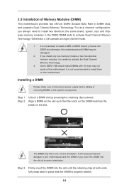
2. If you install only one memory module or two non-identical memory modules, it is unable to activate the Dual Channel Memory Technology.
3. Some DDR3 1GB double-sided DIMMs with 16 chips may not work on this motherboard. It is not recommended to install them on this motherboard.
Installing a DIMM
Please make sure to disconnect power supply before adding...
User Manual - Page 16
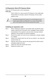
... are 2 PCI Express slots on this motherboard. PCIE slots:
PCIE1 (PCIE 2.0 x1 slot) is used for PCI Express x1 lane width cards. PCIE2 (PCIE 3.0 x16 slot) is used for PCI Express x16 lane width graphics cards.
Only PCIE2 slot supports Gen 3 speed. To run the PCI Express in Gen 3 speed, please install an Ivy Bridge CPU. If you install a Sandy Bridge CPU, the PCI Express will...
User Manual - Page 17
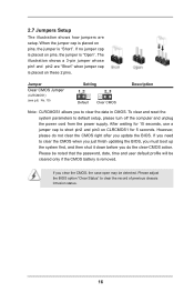
... reset the system parameters to default setup, please turn off the computer and unplug the power cord from the power supply. After waiting for 15 seconds, use a jumper cap to short pin2 and pin3 on CLRCMOS1 for 5 seconds. However, please do not clear the CMOS right after you update the BIOS. If you need to clear...
User Manual - Page 19
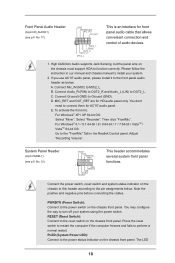
... for front panel audio cable that allows convenient connection and control of audio devices.
1. High Deinition Audio supports Jack Sensing, but the panel wire on the chassis must support HDA to function correctly. Please follow the instruction in our manual and chassis manual to install your system.
2. If you use AC'97 audio panel, please install it to the front panel audio header as below...
User Manual - Page 20
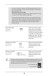
...differ by chassis. A front panel module mainly consists of power switch, reset switch, power LED, hard drive activity LED, speaker and etc. When connecting your chassis front... CPU fan cable to the connector and match the black wire to the ground pin.
Though this motherboard provides 4-Pin CPU fan (Quiet Fan) support, the 3-Pin CPU fan still can work successfully even without the fan speed control ...
User Manual - Page 21
... with Pin 1 and Pin 13.
24
13
20-Pin ATX Power Supply Installation
12
1
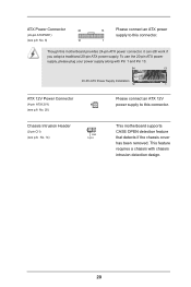
ATX 12V Power Connector
(4-pin ATX12V1) (see p.8 No. 20)
Please connect an ATX 12V power supply to this connector.
Chassis Intrusion Header
(2-pin CI1) (see p.8, No. 14)
1
GND Signal
This motherboard supports CASE OPEN detection feature that detects if the chassis cover...
User Manual - Page 22
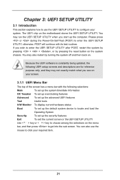
...motherboard stores the UEFI SETUP UTILITY. You may run the UEFI SETUP UTILITY when you start up the computer. Please press or during the Power-On-Self-Test (POST) to enter the UEFI SETUP... display current hardware status
Boot
To set up the default system device to locate and load the
Operating System
Security
To set up the security features
Exit
To exit the current screen or the UEFI SETUP ...
User Manual - Page 24
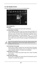
...'s new power saving technology. Processors can switch between multiple frequencies and voltage points to enable power saving. The default value is [Enabled]. Coniguration options: [Enabled] and [Disabled]. If you install Windows® VistaTM / 7 / 8 / 8.1 and want to enable this function, please set this item to [Enabled]. This item will be hidden if the current CPU does not support Intel...
User Manual - Page 29
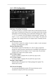
...computer system with an Intel processor that supports Hyper-Threading technology and an operating system that includes optimization for this technology, such as Microsoft® Windows® XP / VistaTM / 7 / 8 / 8.1 is required. Set to [Enabled] if using Microsoft® Windows® XP, VistaTM, 7, 8, 8.1, or Linux kernel version 2.4.18 or higher. This option will be hidden if the installed CPU...
User Manual - Page 30
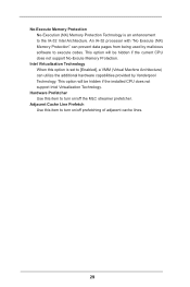
... IA-32 Intel Architecture. An IA-32 processor with "No Execute (NX) Memory Protection" can prevent data pages from being used by malicious software to execute codes. This option will be hidden if the current CPU does not support No-Excute Memory Protection.
Intel Virtualization Technology When this option is set to [Enabled], a VMM (Virtual Machine Architecture...
User Manual - Page 31
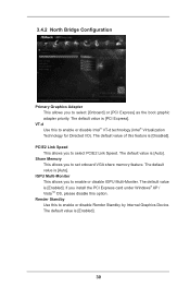
... Graphics Adapter This allows you to select [Onboard] or [PCI Express] as the boot graphic adapter priority. The default value is [PCI Express]....Memory This allows you to set onboard VGA share memory feature. The default value is [Auto].
IGPU Multi-Moniter This allows you to enable or disable IGPU Multi-Moniter. The default value is [Enabled]. If you install the PCI Express card under Windows...
User Manual - Page 38
... system time are required.
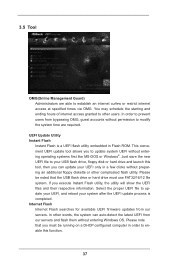
UEFI Update Utility Instant Flash
Instant Flash is a UEFI lash utility embedded in Flash ROM. This convenient UEFI update tool allows you to update system UEFI without entering operating systems irst like MS-DOS or Windows®. Just save the new UEFI ile to your USB lash drive, loppy disk or hard drive and launch this tool, then...
User Manual - Page 45
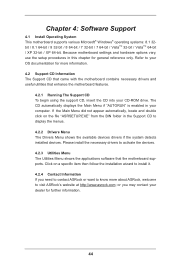
...-ROM drive. The CD automatically displays the Main Menu if "AUTORUN" is enabled in your computer. If the Main Menu did not appear automatically, locate and double click on the ile "ASRSETUP.EXE" from the BIN folder in the Support CD to display the menus.
4.2.2 Drivers Menu The Drivers Menu shows the available devices drivers if the system detects installed devices. Please install...