Acer AL1702 driver and firmware

Related Acer AL1702 Manual Pages
Download the free PDF manual for Acer AL1702 and other Acer manuals at ManualOwl.com
AL1702 Service Guide - Page 5
AL1702
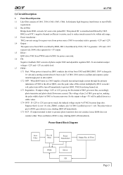
1) Circuit Description
1. PowerBoard Operation 1.1 Line ... and +22V respectively. I804 is the regulator for +5V output. 1.5 Driver : Q803 drive T802 from PWM control of I801 for power converted. 1.6 FB : Negative feedback CKT consists of photo coupler I802 and...off immediately.
Power Board Block Diagram
Line Filter
Rec. & Filter
Power Transformer
Outpur Rec. & Filter
PWM
Driver FB
Page 3
AL1702 Service Guide - Page 6
AL1702
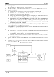
2. InverterOperation This unit operates on an output voltage of 22V from power source.
2.1 VCC: When On/Off pin of P802 is high level input, Q106 turns on and provides +5VDC for I101 power supply. 2.2 Control... striking time. 2.2.5 Dimming control: The divided voltage of R106/R105/R104 control the duty pulse of burst-mode to drive
Q105 and perform a wide dimming control for the CCFL. The ...
AL1702 Service Guide - Page 8

... data transfer between I308 and MCU is effected through the IIC bus SCL (pin14) and SDA (pin13) of MCU. The OSD related setting data, I305 control data and other service data, to be stored in I308.
3.5.6 P308 connector The P308 has support keypad function. Control is give effect to for the push switch to be used...
AL1702 Service Guide - Page 30
5 D C B A
5
4
3
2
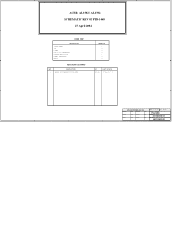
ACER AL1502 / AL1702 SCHEMATIC REV 02 PTB-1468
27 April 2004
ROAD MAP
DESCRIPTION
TITLE SHEET TOP POWER VGA & DDC INTERFACE SCALER MST8111/6B PANEL INTERFACE AUDIO
REVISION HISTORY
REV. 02
DESCRIPTION BASED ON SCHEMATICS FOR ACER
SHEET NO.
1 2 3 4 5 6 7
BY KT.LIN
LAST UPDATE 27 April '04
1 D C B
A
LITE-ON TECHNOLOGY CO.
DRAWN:
Date:
DESIGN:
Date:
CHECK:
Date:...
AL1702 Service Guide - Page 32
... 4
C314
C316
C
AIC1084-33CM
47uF/25V 0.1uF(NC)
47uF/25V 0.1uF(NC)
3
6 PANELVCC_EN
R311
1K
2
Q303
MMBT3904
4K7
C325 0.1uF
VDD15V
Note : If input power is +12V install R378.
R378
1
0(NC)
B
FB305
B
PBY201209T-121Y-S(NC)
TO-252
I303
VCC12V
VCC12V
FB307
PBY201209T-121Y-S(NC)
I313 AO3401(NC)
2
3
VLCD12V FB308 PBY201209T-121Y-S(NC...
AL1702W Service Guide - Page 3
... in a retrieval system, or translated into any language or computer language, in any form or by any means, electronic, mechanical, magnetic, optical, chemical, manual or otherwise, without the prior written permission of Acer Incorporated.
Disclaimer The information in this guide is subject to change without notice. Acer Incorporated makes no representations or warranties, either expressed or...
AL1702W Service Guide - Page 4
... FRU list of this printed Service Guide. You MUST use the list provided by your regional Acer office to order FRU parts for repair and service of customer machines.
Warning: (For FCC Certified Models)
Note: This equipment has been tested and found to comply with the limits for a Class B digital device, pursuant to Part 15 of...
AL1702W Service Guide - Page 5
...power outlet as a safety feature. If your outlet does not accommodate the three-wire plug, have an electrician install the correct outlet, or use an adapter...servicing to qualified service personnel z To ensure satisfactory operation, use the monitor only with UL listed computers which have appropriate configured receptacles marked between 100 - 240V AC, Min. 5A. z The wall socket shall be installed...
AL1702W Service Guide - Page 6
... 1 Monitor Features
Introduction Electrical Requirements LCD Monitor General Specification LCD Panel Specification Support Timing Monitor Block Diagram Main Board Diagram Software Flow chart Main Board Layout Adjusting the viewing angle Rear Bezel
Chapter 2 Operating Instructions
External Controls Front Panel Controls Adjusting the picture OSD Message LOGO
Chapter 3 Machine Disassembly
Chapter...
AL1702W Service Guide - Page 17
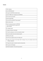
... AUTO and SELECT keys pressed? 8) Enter factory mode. 9) Save the power key status into EEPROM.
Turn on the LED and set it to green color. Scalar initializes. 10) In standby mode? 11) Update the lifetime of back light. 12) Check the analog port, are there any signals coming? 13) Does the scalar send out...
AL1702W Service Guide - Page 23
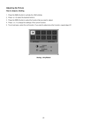
Adjusting the Picture
How to Adjust a Setting 1. Press the MENU-button to activate the OSD window. 2. Press to select the desired function. 3. Press the MENU-button to select the function that you want to adjust. 4. Press < or > to change the settings of the current function. 5. To exit and save, select the exit function. If...
AL1702W User's Guide - Page 1
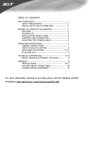
... LCD MONITORS 3
BEFORE YOU OPERATE THE MONITOR 3 FEATURES 3 PACKING LIST 3 INSTALLATION INSTRUCTIONS 4 CONTROLS AND CONNECTORS 5 ADJUSTING THE VIEWING ANGLE 6
OPERATING INSTRUCTIONS 7 GENERAL INSTRUCTIONS 7 HOW TO ADJUST A SETTING 9 ADJUSTING THE PICTURE 10-11 PLUG AND PLAY 12
TECHNICAL SUPPORT(FAQ 13-14 ERROR MESSAGE & POSSIBLE SOLUTION --------- 15
APPENDIX 16 SPECIFICATIONS 16-17...
AL1702W User's Guide - Page 2
... for a Class B digital device, pursuant to Part 15 of the FCC Rules. These limits are designed to provide reasonable protection against harmful interference in a residential installation. This equipment generates, uses... interface cables and AC power cord, if any, must be used in order to comply with the emission limits.
3. The manufacturer is not responsible for any radio or TV interference caused...
AL1702W User's Guide - Page 3
... kit approved by the manufacturer and follow the kit instructions.
z Slots and openings in the back and bottom... a grounded power outlet as a safety feature. If your outlet does not accommodate the three-wire plug, have an electrician install the correct... refer all servicing to qualified service personnel.
z To ensure satisfactory operation, use the monitor only with UL listed computers which have ...
AL1702W User's Guide - Page 4
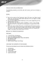
... screen depending on the
desktop pattern you use.
...Display for Windows • Recommened Resolutions: 1440 X 900 @60Hz • EPA ENERGY STAR® • Ergonomic Design • Space Saving, Compact Case Design
CHECKING THE CONTENTS OF THE PACKAGE
The product package should include the following items:
1. LCD Monitor 2. Owner's Manual 3. Power Cord 4. 15-pin D-Sub Cable 5 . Quick Start Guide...
AL1702W User's Guide - Page 5
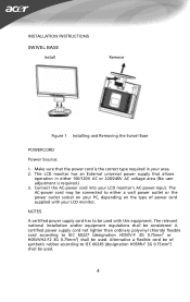
INSTALLATION INSTRUCTIONS
SWIVEL BASE IVEL BASE
Install
Remove
Figure 1 Installing and Removing the Swivel Base
POWERCORD
Power Source:
1. Make sure that the power cord is the correct type required in your area. 2. This LCD monitor has an External universal power supply that allows
operation in either 100/120V AC or 220/240V AC voltage area (No user adjustment...
AL1702W User's Guide - Page 9
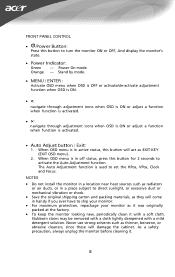
FRONT PANEL CONTROL
• /Power Button:
Press this button to turn the monitor ON or OFF, And display the monitor's state.
• Power Indicator:
Green - Power On mode. Orange - Stand by mode.
&#...the Auto Adjustment function. The Auto Adjustment function is used to set the HPos, VPos, Clock and Focus.
NOTES
• Do not install the monitor in a location near heat sources such as radiators
or...
AL1702W User's Guide - Page 10
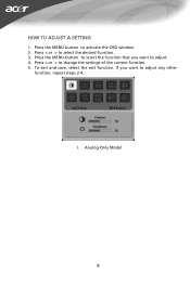
HOW TO ADJUST A SETTING
1. Press the MENU-button to activate the OSD window. 2. Press < or > to select the desired function. 3. Press the MENU-button to select the function that you want to adjust. 4. Press < or > to change the settings of the current function. 5. To exit and save, select the exit function. If you want to adjust any other
function, repeat steps 2-4.
I. Analog-Only Model
9