Asus AP110 driver and firmware

Related Asus AP110 Manual Pages
Download the free PDF manual for Asus AP110 and other Asus manuals at ManualOwl.com
AP110 User Manual - Page 2
... are released for each product design represented by the digit before and after the period of the manual revision number. Manual updates are represented by the third digit in the manual revision number. For previous or updated manuals, BIOS, drivers, or product release information, contact ASUS at http://www.asus.com.tw or through any of the means indicated on the following...
AP110 User Manual - Page 3
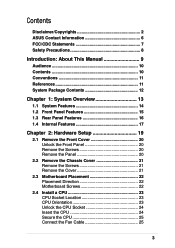
... Panel 20 Remove the Screws 20 Remove the Panel 20
2.2 Remove the Chassis Cover 21 Remove the Screws 21 Remove the Cover 21
2.3 Motherboard Placement 22 Placement Direction 22 Motherboard Screws 22
2.4 Install a CPU 23 CPU Socket Location 23 CPU Orientation 23 Unlock the CPU Socket 24 Insert the CPU 24 Secure the CPU 25 Connect the Fan Cable 25
3
AP110 User Manual - Page 4
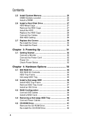
... 34 HDD Tray Frame 35 Hot-swap HDD Tray 35
4.2 Install a Hot-swap HDD 36 Install HDD Tray Frame 36 Remove HDD Tray Cover 37 Install an IDE Drive 38
4.3 RAID Configuration 39 Connect IDE Cables 39 Install a RAID Card 39
4.4 Removing a Hot-swap HDD Tray 40 Connect Power Cables 40
4.5 CD-ROM Drive 41 Remove the CD-ROM Drive 41 Re-install the CD-ROM Drive 42
4
AP110 User Manual - Page 7
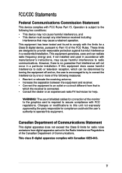
... for a Class B digital device, pursuant to Part 15 of the FCC Rules. These limits are designed to provide reasonable protection against harmful interference in a residential installation. This equipment generates, ...the dealer or an experienced radio/TV technician for help.
WARNING! The use of shielded cables for connection of the monitor to the graphics card is required to assure compliance with...
AP110 User Manual - Page 8
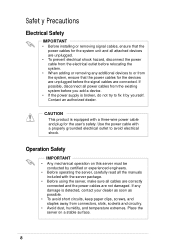
...; Before installing or removing signal cables, ensure that the power cables for the system unit and all attached devices are unplugged.
• To prevent electrical shock hazard, disconnect the power cable from the electrical outlet before relocating the system.
• When adding or removing any additional devices to or from the system, ensure that the power cables for the devices are...
AP110 User Manual - Page 10
... Options This chapter gives information on how to install the optional IDE RAID kit. You will also find the procedure for removing and installing the CD-ROM drive in this chapter.
6. Appendix A: Power Supply Information This appendix gives information on the 250-watt switching power supply that comes with the AP110 server.
7. Appendix B: Troubleshooting This appendix lists the...
AP110 User Manual - Page 11
... for additional information and for product and software updates.
1. ASUS CUV-2LSV Series Motherboard User's Manual This manual contains detailed information about the CUV-2LV motherboard.
2. ASUS Websites The ASUS websites worldwide provide updated information on ASUS hardware and softare products. The ASUS websites are listed in the ASUS Contact Information on page 6.
3. Optional Documentation...
AP110 User Manual - Page 12
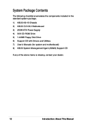
... following checklist enumerates the components included in the standard system package. 1) ASUS AS-15 Chassis 2) ASUS CUV-2LV Motherboard 3) 250W ATX Power Supply 4) 50X CD-ROM Drive 5) 1.44MB Floppy Disk Drive 6) Support CD with Drivers and Utilities 7) User's Manuals (for system and motherboard) 8) ASUS System Management Agent (ASMA) Support CD
If any of the above items is missing, contact your...
AP110 User Manual - Page 17
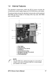
...1. Power Supply 2. Floppy Disk Drive 3. Hot-swap Drive Trays (optional) 4. CD-ROM Drive 5. 3.5-inch Internal Device Bays 6. IDE Cables for Hot-swap Drives (optional) 7. IDE RAID Card (optional) 8. CUV-2LV Motherboard
NOTE
The IDE RAID kit is optional and does not come with all models. If your server includes a RAID kit, it comes already pre-installed in the chassis.
AP110 Server User's Manual
17
AP110 User Manual - Page 19
Chapter 2
This chapter describes the hardware setup procedures that you have to perform when installing system components.
Hardware Setup
AP110 Server User's Manual
19
AP110 User Manual - Page 22
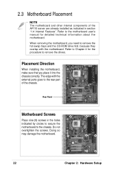
... other internal components of the AP110 server are already installed as indicated in section "1.4 Internal Features". Refer to the motherboard user's manual for detailed technical information about the motherboard. When removing the motherboard, you need to remove the hot-swap trays and the CD-ROM drive first, because they overlap with the motherboard. Refer to Chapter 4 for the procedure...
AP110 User Manual - Page 23
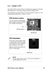
... CUV-2LV motherboard supports a Pentium III/Celeron CPU. This section tells you how to install a CPU. The following pictures show the CPU socket location on the motherboard, and the Pin 1 mark on a CPU.
CPU Socket Location
The CPU socket is located beside the rear panel connectors. Note the Pin 1 location on the socket.
Pin 1
CPU Fan Connector
CPU Socket 370
CPU Orientation
A CPU has...
AP110 User Manual - Page 24
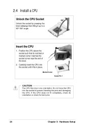
2.4 Install a CPU
Unlock the CPU Socket
Unlock the socket by pressing the lever sideways then lifting it up to a 90°-100° angle.
Insert the CPU
1. Position the CPU above the socket such that its notched or marked corner matches the socket corner near the end of the lever.
2. Carefully insert the CPU into the socket...
AP110 User Manual - Page 25
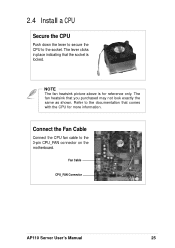
2.4 Install a CPU
Secure the CPU
Push down the lever to secure the CPU to the socket. The lever clicks in place indicating that the socket is ...exactly the same as shown. Refer to the documentation that comes with the CPU for more information.
Connect the Fan Cable
Connect the CPU fan cable to the 3-pin CPU_FAN connector on the motherboard.
Fan Cable
CPU_FAN Connector
AP110 Server User's Manual
25
AP110 User Manual - Page 26
... y
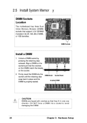
DIMM Sockets Location
The motherboard has three Dual Inline Memory Module (DIMM) sockets that support 3.3V SDRAM modules in 32, 64, 128, 256, 512MB, or 1GB densities.
DIMM Sockets
Install a DIMM
1. Unlock a DIMM ... clips snap back in place and the DIMM is properly seated.
DIMM Notch Socket Break Installed DIMM
CAUTION
DIMMs are keyed with notches so that they fit in only one direction. DO...
AP110 User Manual - Page 27
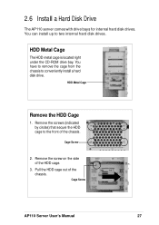
2.6 Install a Hard Disk Drive
The AP110 server comes with drive bays for internal hard disk drives. You can install up to two internal hard disk drives.
HDD Metal Cage
The HDD metal cage is located right under the CD-ROM drive bay. You have to remove the cage from the chassis to conveniently install a hard disk drive.
HDD Metal Cage
Remove the HDD Cage
1. Remove the...
AP110 User Manual - Page 28
2.6 Install a Hard Disk Drive
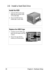
Install the HDD
1. Insert the HDD into the cage (label side up) until the holes on the sides align.
2. Secure the HDD with four screws (two on each side).
Replace the HDD Cage
1. Carefully insert the HDD cage back into the chassis until it fits in place.
2. Secure the cage with the screws you removed earlier.
28
Chapter 2: Hardware Setup
AP110 User Manual - Page 29
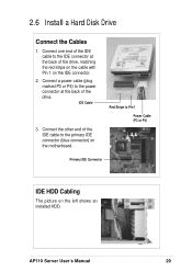
... or P4) to the power connector at the back of the drive.
IDE Cable
3. Connect the other end of the IDE cable to the primary IDE connector (blue connector) on the motherboard.
Red Stripe to Pin 1
Power Cable (P3 or P4)
Primary IDE Connector
IDE HDD Cabling
The picture on the left shows an installed HDD.
AP110 Server User's Manual
29
AP110 User Manual - Page 34
... installation.
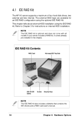
NOTE
The IDE RAID kit is optional and does not come with all models. If your server includes a RAID kit, it comes already pre-installed in the chassis.
IDE RAID Kit Contents
RAID Card
Hot-swap HDD Tray Sets
ATA/100 IDE Screws Security Keys Cables
NOTE
The IDE RAID kit also includes a diskette that contains the IDE drivers and a RAID card user's manual...
AP110 User Manual - Page 49
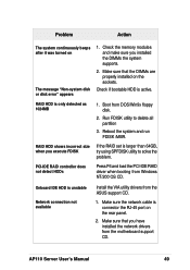
... F6 and load the PCI-IDE RAID driver when booting from Windows NT/200 OS CD.
Onboard IDE HDD is unstable
Network connection not available
Install the VIA utility drivers from the ASUS support CD.
1. Make sure the network cable is connector the RJ-45 port on the rear panel.
2. Make sure that you have installed the network drivers from the motherboard support CD.
AP110 Server User's Manual
49