Asus AP1710-I5 driver and firmware

Related Asus AP1710-I5 Manual Pages
Download the free PDF manual for Asus AP1710-I5 and other Asus manuals at ManualOwl.com
AP1710-I5 English Manual - Page 2
... WITHOUT NOTICE, AND SHOULD NOT BE CONSTRUED AS A COMMITMENT BY ASUS. ASUS ASSUMES NO RESPONSIBILITY OR LIABILITY FOR ANY ERRORS OR INACCURACIES THAT MAY APPEAR IN THIS MANUAL, INCLUDING THE PRODUCTS AND SOFTWARE DESCRIBED IN IT.
Copyright © 2003 ASUSTeK COMPUTER INC. All Rights Reserved.
Product Name: AP1710-I5 Manual Revision: First Edition E1304 Release Date: June 2003
ii
ASUS AP1710-I5
AP1710-I5 English Manual - Page 4
... radio/TV technician for help.
WARNING! The use of shielded cables for connection of the monitor to the graphics card is ...digital apparatus does not exceed the Class B limits for radio noise emissions from digital apparatus set out in the Radio Interference Regulations of the Canadian Department of Communications.
This class B digital apparatus complies with Canadian ICES-003.
iv
ASUS AP1710-I5
AP1710-I5 English Manual - Page 5
...Disclaimer/Copyrights ii ASUS Contact Information iii FCC/CDC Statements iv Safety Precautions vii Electrical Safety vii Operation Safety vii
Introduction
About this guide I-1
Audience ...and installing chassis cover 2-2 2.2 Motherboard installation 2-4 2.3 Central Processing Unit 2-5 2.4 System Memory 2-9 2.5 Fixed Device Bays 2-12 2.6 Installing a Hard Disk Drive 2-18
User's Manual
...
AP1710-I5 English Manual - Page 6
... Expansion Card Slot 2-23 2.8 Long Card Support Guide 2-24 2.9 RAID Card 2-25 2.10 Hard Drive Blower 2-26 2.11 Chassis Fan 2-27 2.12 Connecting Cables 2-28 2.13 SCSI Backplane 2-29
Appendix A: Optional chassis roller-wheel
Chassis Roller-wheel Installation A-2
Appendix B: Power Modules
Redundant Power Modules A-4
Appendix C: Troubleshooting
Troubleshooting A-9
vi
ASUS AP1710-I5
AP1710-I5 English Manual - Page 7
...; Before installing or removing signal cables, ensure that the power cables for the system unit and all attached devices are unplugged.
• To prevent electrical shock hazard, disconnect the power cable from the electrical outlet before relocating the system.
• When adding or removing any additional devices to or from the system, ensure that the power cables for the devices are...
AP1710-I5 English Manual - Page 10
... hardware operation and specifications of the AP1710-I5 redundant power modules. 6. Appendix C: Troubleshooting This appendix lists the common problems that you may encounter while using the AP1710-I5 server. It lists the possible causes of the problems and offers solutions. You may refer to this part and try to solve simple problems before calling customer support.
I-2
ASUS AP1710-I5
AP1710-I5 English Manual - Page 11
...sources for additional information and for product and software updates.
1. ASUS PRL-DL Motherboard User's Manual This manual contains detailed information about the PRL-DL motherboard.
2. ASUS Websites The ASUS websites worldwide provide updated information on ASUS hardware and softare products. The ASUS websites are listed in the ASUS Contact Information on page v.
3. Optional Documentation Your...
AP1710-I5 English Manual - Page 12
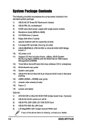
... IDE hard disk drive tray (6 units) 9) ASUS BBATA2U3, ATA133 IDE to Ultra160 SCSI HDD Bridge
board x 1 10) AC power cord 11) Support CD that includes drivers, utilities, ASUS System
Monitoring Agent (ASMA) with the ASUS Server Web-based Management (ASWM) 12) Trend Micro ServerProtect Anti-virus software CD for enterprises 13) Motherboard user guide 14) System user guide 15) ASUS PCI-SCU3 Ultra160...
AP1710-I5 English Manual - Page 15
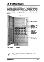
... hard disk drives. The power and reset buttons, LED indicators, optical drive, floppy drive and two USB connectors are also located on the front panel. For future installation of 5.25 devices, there are two drive bays available. The front panel of the server is protected by a door and lock for added security.
CD-ROM Drive
3.5" Floppy Drive
2 empty 5.25" bays Status LED Drive Activity...
AP1710-I5 English Manual - Page 19
Chapter 2
Hardware Setup
This chapter lists the hardware setup procedures that you have to perform when installing system components.
User's Manual
2-1
AP1710-I5 English Manual - Page 20
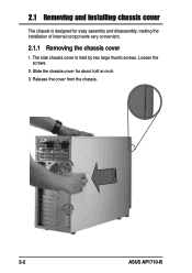
2.1 Removing and installing chassis cover
The chassis is designed for easy assembly and disassembly, making the installation of internal components very convenient.
2.1.1 Removing the chassis cover
1. The side chassis cover is held by two large thumb screws. Loosen the screws.
2. Slide the chassis cover for about half an inch. 3. Release the cover from the chassis.
2-2
ASUS AP1710-I5
AP1710-I5 English Manual - Page 21
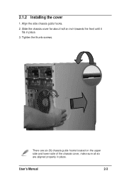
2.1.2 Installing the cover
1. Align the side chassis guide hooks. 2. Slide the chassis cover for about half an inch towards the front until it
fits in place. 3. Tighten the thumb screws.
There are six (6) chassis guide hooks located on the upper side and lower side of the chassis cover, make sure all six are aligned properly in place.
User's Manual
2-3
AP1710-I5 English Manual - Page 22
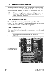
... external ports goes to the rear part of the chassis as indicated in the image below.
2.2.2 Screw holes
Place screws into the holes indicated by circles to secure the motherboard to the chassis.
Do not overtighten the screws! Doing so may damage the motherboard.
Place this side towards the rear of the chassis
2-4
ASUS AP1710-I5
AP1710-I5 English Manual - Page 23
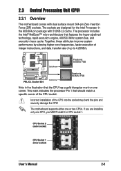
.... This mark indicates the processor Pin 1 that should match a specific corner of the CPU socket.
Incorrect installation of the CPU into the socket may bend the pins and severely damage the CPU!
The motherboard supports either one or two CPUs. If you are installing only one CPU, you MUST install it in CPU socket 1.
CPU Socket 2 (outer socket)
CPU Socket 1 (inner socket)
User's Manual
2-5
AP1710-I5 English Manual - Page 24
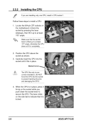
... orientation. DO NOT force the CPU into the socket to prevent bending the pins and damaging the CPU!
4. When the CPU is in place, press it firmly on the socket while you push down the socket lever to secure the CPU. The lever clicks on the side tab to indicate that it is locked.
2-6
ASUS AP1710-I5
AP1710-I5 English Manual - Page 25
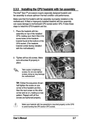
...; Xeon™ processors require especially designed heatsink and fan assembly to ensure optimum thermal condition and performance.
Make sure that the heatsink with fan assembly is properly installed on the motherboard. A tilted or improperly installed heatsink with fan assembly can cause damage to motherboard CPU socket and/or CPU. Follow these steps to install the CPU heatsink and fan...
AP1710-I5 English Manual - Page 26
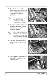
... assembly is stable in place and the fan power cable are connected properly.
Don't forget to connect the CPU fan cable. Hardware monitoring errors may occur if you fail to plug the fan cable.
5. If you wish to install two CPUs, repeat the same steps for CPU socket 2.
6. Use CPUFAN2 connector for the second CPU heatsink and fan assembly cable.
2-8
ASUS AP1710-I5
AP1710-I5 English Manual - Page 31
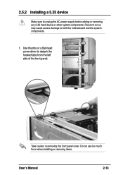
2.5.2 Installing a 5.25 device
Make sure to unplug the AC power supply before adding or removing any 5.25 fixed device or other system components. Failure to do so may cause severe damage to both the motherboard and the system components.
1. Use thumbs or a flat-head screw driver to detach the hooked tabs from the left side of the...
AP1710-I5 English Manual - Page 42
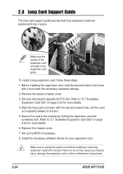
... Card Slot" on page 2-23 for more details.
6. Replace the chassis cover.
7. Set up the BIOS if necessary.
8. Install the necessary software drivers for your expansion card.
Make sure to unplug the power cord before installing or removing expansion cards from the slot. Failure to do so may cause you physical injury, damage the expansion card or other motherboard components.
2-24
ASUS AP1710-I5
AP1710-I5 English Manual - Page 59
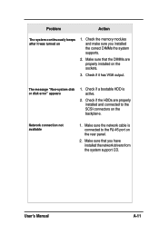
...-system disk or disk error" appears
1. Check if a bootable HDD is active.
2. Check if the HDDs are properly installed and connected to the SCSI connectors on the backplane.
Network connection not available
1. Make sure the network cable is connected to the RJ-45 port on the rear panel.
2. Make sure that you have installed the network drivers from the system support CD.
User's Manual...