Asus AP8000 driver and firmware


Related Asus AP8000 Manual Pages
Download the free PDF manual for Asus AP8000 and other Asus manuals at ManualOwl.com
Hardware Reference - Page 2
... are released for each product design represented by the digit before and after the period of the manual revision number. Manual updates are represented by the third digit in the manual revision number.
For previous or updated manuals, BIOS, drivers, or product release information, contact ASUS at http://www.asus.com.tw or through any of the means indicated on the following...
Hardware Reference - Page 4
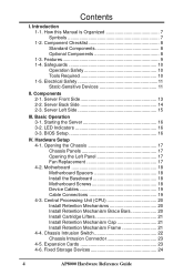
... LED Indicators 16 3-3. BIOS Setup 16
IV. Hardware Setup 4-1. Opening the Chassis 17 Chassis Panels 17 Opening the Left Panel 17 Fan Replacement 17 4-2. Motherboard 18 Motherboard Spacers 18 Install the Baseboard 18 Motherboard Screws 18 Device Cables 19 Cable Connections 19 4-3. Central Processing Unit (CPU 20 Install Retention Mechanisms 20 Install Retention Mechanism Brace Bars...
Hardware Reference - Page 5
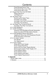
Contents
Fixed Storage Device Tray 24 Fixed Device Bay Cover Clips 24 Fixed Device Bay Cover 24 4-7. Floppy Disk Drive and CD-ROM 25 Floppy Disk Drive 25 CD-ROM Drive 25 4-8. Hot-Swap Trays 26 Removing Hot-Swap Trays 26 Hot-Swap Tray Usage 26 Hot-Swap Tray Front Connections 27 Hot-Swap Tray Interface 27 4-9. Hot-Swap Tray Connector Board 28...
Hardware Reference - Page 6
...expressly approved by the party responsible for compliance could void the user's authority to operate this equipment.
Canadian Department of Communications Statement
This digital apparatus does not exceed the Class B limits for radio noise emissions from digital apparatus set out in the Radio Interference Regulations of the Canadian Department of Communications.
6
AP8000 Hardware Reference Guide
Hardware Reference - Page 7
... MUST be followed in order to complete a task. NOTE: Tips and information to aid in completing a task. PHILIP (CROSS) SCREW DRIVER: Tools required to install or remove the components in this server. STANDARD (FLAT) SCREW DRIVER: Tools required to install or remove the components in this server. STEP: Actions to complete a task
AP8000 Hardware Reference Guide
7
Hardware Reference - Page 10
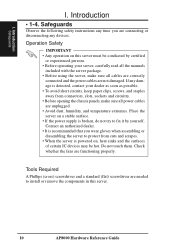
.... • When the server is powered on, heat sinks and the surfaces of certain IC devices may be hot. Do not touch them. Check whether the fans are functioning properly.
Tools Required
A Phillips (cross) screwdriver and a standard (flat) screwdriver are needed to install or remove the components in this server.
10
AP8000 Hardware Reference Guide
Hardware Reference - Page 11
....
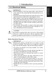
CAUTION
This product is equipped with a three-wire power cable and plug for the user's safety. Use the power cable in conjunction with a properly grounded electrical outlet to avoid electrical shock.
Static-Sensitive Devices
IMPORTANT Motherboards, adapters, and disk drives are sensitive to static electricity discharge. These devices are wrapped in antistatic bags to prevent this damage...
Hardware Reference - Page 16
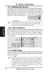
... any pre-installed software. When booting your server for the first time, make BIOS settings by following the motherboard User's Manual.
NOTE When installing Windows NT 4.0, use the Windows NT installation disks. Installing from the CD will require you to pre-install SCSI drivers by pressing F6 before setup begins. You may need device drivers on a floppy disk in order to install devices during the...
Hardware Reference - Page 17
...screws on the back of the server (as circled) and also by a CAM.
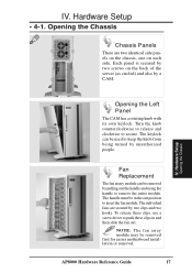
IV. Hardware Setup
Opening the Chassis
Opening the Left Panel
The CAM has a rotating knob with its own keylock. ... these clips, use a screw driver to push these clips in and then slide the fan out.
NOTE: The fan array module may be removed first for easier motherboard installation or removal.
AP8000 Hardware Reference Guide
17
Hardware Reference - Page 18
... in the areas circled on the chassis.
IV. Hardware Setup
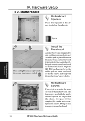
Motherboard
Spacer
Place and tighten three captive nuts in the corner locations as circled.
Install the Baseboard
A metal baseboard is required to add stability to the motherboard. A rubber pad is placed between the metal board and motherboard to prevent shorting. Align the rubber pad over the...
Hardware Reference - Page 20
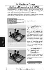
IV. Hardware Setup
• 4-3. Central Processing Unit (CPU)
This server supports two processors which requires one retention mechanism for each processor. Before installing the CPU, secure the motherboard on the rubber pad and metal baseboard. (See page 18.)
When only one processor is used, the other Slot 2 connector must be terminated with the provided front side bus termination module.
...
Hardware Reference - Page 21
... into place.
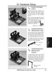
Two Dots
One Dot
Install Retention Mechanism Frame
A metal frame is used accross both retention mechanisms. After installing the frame, four captive nuts should be tightened on the feet of the frame to the screws protruding from the re-
tention mechanisms.
IV. Hardware Setup
CPU
Sticker faces the CPU fan
AP8000 Hardware Reference Guide
21
Hardware Reference - Page 22
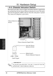
... is opened. The connection diagram is given here.
Chassis Intrusion Switch
IV. Hardware Setup
Chassis Intrusion Switch
Chassis Intrusion Signal Cable
from the Chassis Intrusion Switch
+5VSB GND Chasis Signal
Motherboard's Chassis Intrusion Connector
IMPORTANT
To prevent misconnection, one pin is removed from the motherboard's chassis intrusion connector.
22
AP8000 Hardware Reference Guide
Hardware Reference - Page 23

.... Up to 5 PCI or 1 ISA cards can be installed. One AGP slot is also available for an AGP graphics adapter to provide hardware 3D acceleration and free up an extra PCI slot.
IV. Hardware Setup
Expansion Cards
Contact
CAUTION
Make sure that the total amperage of your installed expansion cards does not exceed the system power specification.
AP8000 Hardware Reference Guide
23
Hardware Reference - Page 24
IV. Hardware Setup
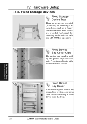
• 4-8. Fixed Storage Devices
Fixed Storage Device Tray
There are six screws provided (as circled) for mounting a 4inch device such as a floppy or hard disk drive. Four screws are provided (as boxed) for mounting a 6-inch device such as a CD-ROM or tape drive.
Fixed Device Bay Cover Clips
The device bay panel is held by two plastic clips on each side...
Hardware Reference - Page 25
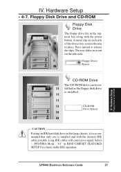
...drive is installed.
CD-ROM Drive Spacer
IV. Hardware Setup
Floppy Drive & CD-ROM
CAUTION
If using an IDE hard disk drive in this large chassis, it is recommended that only one is installed and with the shortest IDE cable possible. Long IDE cables will cause poor signal. Select "...PIO/DMA Mode : 3/1" in BIOS CHIPSET FEATURES SETUP for a more stable IDE operation.
AP8000 Hardware Reference Guide...
Hardware Reference - Page 30
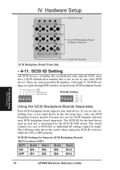
... board supports four hard drives. If you are only installing four or less hard drives in the hot-swap bays, only one SCSI backplane board is needed. You may also use two SCSI channels and treat each SCSI backplane board separately. The SCSI ID for the hard drives used in each slot is determined by the SCSI ID DIP switch. The switch controls two sets...
Hardware Reference - Page 31
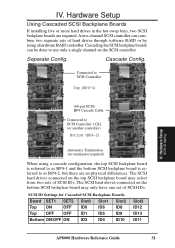
... SCSI controller can combine two separate sets of hard drives through software RAID or by using a hardware RAID controller. Cascading the SCSI backplane boards can be done to use only a single channel on the SCSI controller.
Separate Config.
Cascade Config.
Connected to SCSI Controller
Top (BP4-1)
IV. Hardware Setup
SCSI ID Setting
(68-pin SCSI) BP4 Cascade Cable
Connected to SCSI Controller...
Hardware Reference - Page 32
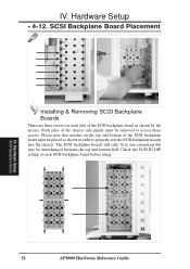
... the SCSI backplane board must be placed as shown in order to properly seat the SCSI backplane boards into the chassis. The SCSI backplane boards will only fit in one orientation but may be interchanged between the top and bottom half. Check the SCSI ID DIP setting of each SCSI backplane board before using.
IV. Hardware Setup
SCSI Backplane Board
32
AP8000 Hardware Reference Guide
Hardware Reference - Page 43
... several drives for increased performance). A RAID card is required to setup a RAID system.
RAM (Random Access Memory) There are several different types of RAM such as DRAM (Dynamic RAM), EDO DRAM (Extended Data Out DRAM), SDRAM (Synchronous DRAM).
ROM (Read Only Memory) ROM is nonvolatile memory used to store permanent programs (called firmware) used in certain computer components. Flash ROM (or...