Canon PC940 driver and firmware

Related Canon PC940 Manual Pages
Download the free PDF manual for Canon PC940 and other Canon manuals at ManualOwl.com
Service Manual - Page 3
... in the field so as to ensure their quality and performance.
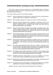
This service manual consists of the following chapters:
Chapter 1 General Description introduces the machine's features, specifications, names of parts, and how originals are reproduced.
Chapter 2 Basic Operation explains how copies are made on a step-by-step basis.
Chapter 3
Exposure System discusses the...
Service Manual - Page 9

...
H. Controlling the Belt Motor .. 8-15 I. Detecting Original Jams ..... 8-16 J. Power Supply 8-17 II. DISASSEMBLY/ASSEMBLY ..... 8-18 A. Removing the ADF 8-19 B. External Covers 8-21 C. Drive System 8-23 D. Feeding System 8-26 E. Electrical System 8-33
CHAPTER 9 INSTALLATION
I. SELECTING A SITE 9-1 II. UNPACKING AND
INSTALLATION 9-2 A. Unpacking and Installation ....9-2
B. Placing Copy...
Service Manual - Page 38

...thermistor
Control panel
Main motor Main driver PCB motor
Solenoid
• Pickup clutch solenoid • Registration clutch solenoid • Lens solenoid • Multifeeder pickup solenoid • Cassette pickup solenoid
Side blanking lamp
Power switch
Scanner/ lens drive motor
Scanner cooling fan
Sensor/ switch
ADF
ADF load
Figure 2-102
2-2
COPYRIGHT © 1999 CANON INC.
CANON...
Service Manual - Page 42

... is rotating at a specific speed, the main motor driver PCB keeps sending
the constant speed state signal (MLOCK=0) to the DC controller PCB. If the rotation of the motor starts to have fluctuations, the MLOCK signal goes '1'.
Related Error Code
E010 While the main motor drive signal is generated, the rotation of the main...
Service Manual - Page 45
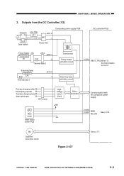
... roller Developing cylinder Transfer charging roller Static eliminator
HVT board
M1
Main motor
Main motor driver PCB
Highvoltage circuit block
+24V
Microprocessor
Communication with the composite power supply
J103-6 MMD J104-1 MLOCK
See p. 2-5.
M2
Scanner/ lens drive motor
Figure 2-107
See p. 3-7.
COPYRIGHT © 1999 CANON INC.
CANON PC800s/900s REV.0 AUG. 1999 PRINTED IN JAPAN...
Service Manual - Page 54

... reproduction ratio in normal copying (312mm/sec, about ...drive motor dives the lens drive system as well as the scanner.
M2
SC_COM SC_B* SC_B SC_COM SC_A* SC_A
PS1 Light-blocking plate
Scanner home position signal (SCHP) Scanner home position sensor (PS1)
J110-1 -2 -3 -4 -5 -6
J101-1
Figure 3-104
Q109 Motor driver circuit
DC controller PCB
3-4
COPYRIGHT © 1999 CANON INC.
CANON...
Service Manual - Page 57

.../ off the scanner/lens drive motor (M2) or to switch the direction of its rotation.
(Q101)
DC controller PCB
+24VU R399
J110 SC-COM SC-COM
Microprocessor
A A* B B*
Current switching signal 1 Current switching signal 2 Current switching signal 3
(Q109)
Motor driver circuit
SC-A SC-A*
SC-B
SC-B*
M2
COPYRIGHT © 1999 CANON INC.
CANON PC800s/900s REV.0 AUG...
Service Manual - Page 58

CHAPTER 3 EXPOSURE SYSTEM
b. Operations The microprocessor (Q101) mounted on the DC controller PCB receives instructions from the
control panel PCB copying mode settings (e.g., reproduction ratio). In response, it applies drive pulses to the scanner/lens drive motor (M2) through the motor driver circuit.
The scanner motor is a 4-phase stepping motor, and changes the direction and speed of its ...
Service Manual - Page 183

...)
DC power supply circuit
Fixing heater control circuit
Scanning lamp control circuit
Highvoltage power supply circuit
+5V Control panel
+24VR
AE sensor
To ADF
+5V Sensor
+5V +24VU +24VR
DC +24VU controller
PCB +24VU
Solenoid
Scanner/lens drive motor (M2)
+24VU Scanner cooling fan
+24VU Blanking lamp
+24VU Main motor/ main motor M1 driver PCB
Fixing heater
Scanning lamp
Primary...
Service Manual - Page 198

CHAPTER 7 EXTERNALS/AUXILIARY MECHANISMS
5) Detach the fan belt [4].
6) Remove the four screws [5], and detach the main motor unit [6].
Caution: When installing the main motor unit, be sure to attach the fan belt. After attaching the fan belt, make sure that the belt is free of twists.
[4]
...
Service Manual - Page 200

... the five screws [5], and detach the main drive assembly [6].
Caution: When installing the main drive assembly, be sure to attach the fan belt. After attaching the fan belt, make sure that the belt is free of twists.
[4]
Figure 7-324
[6] [5]
[5]
Figure 7-325
7-20
COPYRIGHT © 1999 CANON INC.
CANON PC800s/900s REV.0 AUG. 1999 PRINTED IN...
Service Manual - Page 220

... pickup faults. Any pickup fault causes the ADF controller to flash the JAM indicator on the copier and stop the pickup motor at the same time.
ADF controller PCB +24V
Q1 CPU
PM1 PM0
Q5 Motor driver
PMRD1 PMRD1*
Pickup motor
M2
Figure 8-121
Motor drive signal (PM0)
'1' '1' '0' '0'
Motor drive signal (PM1)
'1' '0' '1' '0'
Table 8-102
Pickup roller rotation...
Service Manual - Page 221

... faults. Any feeding fault will cause the ADF controller to flash the Jam indicator on the controller and stop the belt motor at the same time.
Q1
A
CPU
A*
B
B*
ADF controller PCB
+24V
MA Q4 Motor driver MA*
MB
MB*
Belt motor M1
Figure 8-122
COPYRIGHT © 1999 CANON INC.
CANON PC800s/900s REV.0 AUG. 1999 PRINTED IN JAPAN...
Service Manual - Page 241

CHAPTER 9 INSTALLATION
I. SELECTING A SITE 9-1 II. UNPACKING AND
INSTALLATION 9-2 A. Unpacking and Installation ....9-2
B. Placing Copy Paper 9-9 III. MOVING THE MACHINE .......... 9-12
COPYRIGHT © 1999 CANON INC.
CANON PC800s/900s REV.0 AUG. 1999 PRINTED IN JAPAN (IMPRIME AU JAPON)
Service Manual - Page 243

... A SITE
Keep the following in mind when selecting a site for installation; if possible, visit the user's before delivery of the machine:
• The site offers a power outlet whose rating is as specified (±10%) and which may be used... the machine.
10cm min.
Figure 9-101
10cm min.
COPYRIGHT © 1999 CANON INC.
CANON PC800s/900s REV.0 AUG. 1999 PRINTED IN JAPAN (IMPRIME AU JAPON)
9-1
Service Manual - Page 244

... before starting to install it.
A. Unpacking and Installation
Step 1
2
Work
Checks and remarks
Take out the copier and the attachments from the shipping box, and check to make sure that none is missing:
• Cassette • Copy tray • Power cord • ADF auxiliary tray (ADF type only) • User's Manual • Manual feed tray (for...
Service Manual - Page 245
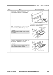
... the shipping attachment [2] (black screw) from the right side of the machine.
CHAPTER 9 INSTALLATION Checks and remarks
Shipping attachment [2]
You will be storing the shipping attachment [2] inside the machine in step 9.
5 Take out the protective member from the manual feed tray. (Multifeeder type only)
Protective member
Caution: This step applies only if...
Service Manual - Page 246

CHAPTER 9 INSTALLATION
Step 6
Work
Open the copyboard cover, and remove the protective sheet. (Copyboard type only)
Caution: If the protective sheet is not fond ... the machine, go to the next step.
Checks and remarks
Protective sheet
Protective members Open/close lever
Protective member
9-4
COPYRIGHT © 1999 CANON INC.
CANON PC800s/900s REV.0 AUG. 1999 PRINTED IN JAPAN (IMPRIME AU JAPON)
Service Manual - Page 247

Step 8
Work
Pick the fixing member from the bottom of the top unit, and detach it.
CHAPTER 9 INSTALLATION Checks and remarks
9 Store the shipping attachments [1] and [2] removed in steps 3 and 4 in the machine's bottom unit...facing up, shake it several times in both directions (90°).
COPYRIGHT © 1999 CANON INC.
CANON PC800s/900s REV.0 AUG. 1999 PRINTED IN JAPAN (IMPRIME AU JAPON)
9-5
Service Manual - Page 248
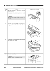
CHAPTER 9 INSTALLATION
Step 12
Work
Place the cartridge on a level place, and pull off the open seal. Holding the tab, pull it straight out in the direction ... the machine to close it fully.
15 Open the original tray.
Caution: This step applies to the ADF type only.
Original tray
9-6
COPYRIGHT © 1999 CANON INC.
CANON PC800s/900s REV.0 AUG. 1999 PRINTED IN JAPAN (IMPRIME AU JAPON)