Dell PowerEdge 2100 driver and firmware

Related Dell PowerEdge 2100 Manual Pages
Download the free PDF manual for Dell PowerEdge 2100 and other Dell manuals at ManualOwl.com
Service Manual - Page 5

... 2-3
bracket, hard-disk drive, removal, 4-10
C
cables, DC power, 1-12 CD-ROM drive
access indicator location, 1-3 location, 1-4, 4-7 removal, 4-8 computer back/left side internal view, 1-5 cover removal, 4-3 front/right side internal view, 1-4 orientation, 1-3 technical specifications, 1-19 configuration guidelines, SCSI drives, 1-7 connectors, locations, 1-14, 4-14
control panel assembly location...
Service Manual - Page 12

...Disk Drive Removal 4-10 Figure 4-9. Expansion Card Removal 4-11 Figure 4-10. Power Supply Removal 4-12 Figure 4-11. System Cooling-Fan Removal 4-13 Figure 4-12. System Board Components 4-14 Figure 4-13. DIMM Removal 4-15 Figure 4-14. DIMM Installation... 1-18 Technical Specifications 1-19 POST Beep Codes 3-1 System Error Messages 3-3 Key Functions A-2 Main Menu Categories A-4 Boot ...
Service Manual - Page 15

... and all other elements of the basic computer system. The microprocessor module is installed in a zero insertion force (ZIF) socket on the system board. This allows upgrading of the system board to a faster, more powerful microprocessor when one becomes available. Contact Dell for information about Dell-supported microprocessor upgrades. The Pentium Pro microprocessor contains a built-in...
Service Manual - Page 16

... VGA-compatible video subsystem attached to the PCI bus with
1 MB video memory standard
• BIOS in upgradable flash memory attached to the EISA bus • Integrated super I/O controller attached to the EISA bus, provides a
bidirectional parallel port, two serial ports, and the diskette drive interface
• Integrated ultra (fast-20) wide small computer system interface (SCSI)
controller...
Service Manual - Page 20

... ECC feature is built into the memory controller on the system board. See "DIMMs" in Chapter 4 for information on removing and replacing DIMMs.
Advanced Expansion Subsystem
The computer system offers advanced expansion subsystems that can support a mixture of traditional EISA expansion cards, Plug and Play ISA expansion cards, and PCI expansion cards. The EISA Configuration Utility included with...
Service Manual - Page 21

...board. The integrated SCSI controller attaches to the PCI bus to provide a high-performance SCSI bus. The integrated SCSI controller provides control for the three SCSI hard-disk drives in the SCSI hard-disk drive cage, the CD-ROM drive in the middle externally-accessible drive bay and a SCSI drive installed in the lower externally-accessible drive bay.
SCSI Hard-Disk Drives
A SCSI hard-disk drive...
Service Manual - Page 22

... devices installed in the external drive bays will require SCSI ID numbers less than 7. When SCSI devices are shipped from Dell, the default SCSI ID numbers are assigned as follows:
• The computer's built-in SCSI controller is configured through the BIOS as
SCSI ID 7 (the default ID number for a host adapter) if the system includes a CD-ROM or tape drive. NOTE: If only wide SCSI hard-disk...
Service Manual - Page 23

• If you install an optional SCSI controller card to control the CD-ROM drive
and any other SCSI device in the externally-accessible drive bays, you must enable termination for the SCSI controller card and the SCSI device at the end of the SCSI interface cable (preferably the CD-ROM drive). See the documentation that came with your SCSI controller card for instructions. Figure 1-5 shows an ...
Service Manual - Page 30

... settings.
Integrated VGA controller enable/disable
Used for trouble shooting
Remove the jumper and use the EISA Configuration Utility to configure the system.
Install to enable the integrated VGA controller.
Install the jumper to boot system from BIOS expansion card.
Remove the jumper to allow normal boot operation from BIOS.
1-16 Dell PowerEdge 2100/180 and 2100/200 Systems Service Manual
Service Manual - Page 35

...)
Video
Video type ATI mach64 (264VT) PCI video controller with integrated VGA connector
Video memory (standard 1 MB (not upgradable)
Power
DC power supply: Wattage 230 W Voltage 90 to ....68 kg (39.0 lb)
Environmental
Temperature: Operating 10° to 35°C (50° to 95°F) Storage 40° to 65°C (-40° to 149°F) Relative humidity . . 8% to 80% (noncondensing)...
Service Manual - Page 41

...the card-mounting bracket's retaining screw. 4. Verify that all jumpers are set correctly. For information about these jumpers, see "System Board Jumpers" in Chapter 1. 5. Check all cable ...
Devices within the system unit may require dedicated memory spaces, interrupt levels, or DMA channels, all of which must be allocated during installation of the devices. Because a device may be installed ...
Service Manual - Page 43

... Diagnostics" in Chapter 2.
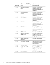
POST Beep Codes
If the monitor cannot display error messages during the POST, the system may emit a series of ...Error
Probable Causes
Invalid Expansioncard-ROM checksum
Improperly seated expansion card or the system needs rebooted.
Invalid BIOS ROM checksum
Corrupted BIOS firmware or defective system board.
DRAM refresh failure
Defective DIMMs or system board...
Service Manual - Page 44
....
Invalid ROM copyright notice
Defective system board.
Unexpected interrupt
Improperly seated expansion card or the system needs rebooted.
Gate A20 failure
Defective system board.
Keyboard controller error
Defective DIMMs or system board. Reseat the DIMMs or replace the system board.
Gate A20 failure
Defective system board.
3-2 Dell PowerEdge 2100/180 and 2100/200 Systems Service Manual
Service Manual - Page 46

....
Invalid CPU speed detected Check jumpers
The microprocessor speed jumper plug may be absent or installed on the wrong jumper pins.
Check the microprocessor speed jumpers.
Memory size limit exceeded
The size of installed DIMM memory is greater than 256 MB.
Verify that the total installed DIMM memory does not exceed 256 MB.
3-4 Dell PowerEdge 2100/180 and 2100/200 Systems Service Manual
Service Manual - Page 55

... be installed in the computer. Refer to this figure when you perform any of the procedures in the following subsections.
diskette drive interface cable
diskette drive interface connector (FLOPPY)
3.5-inch diskette drive CD-ROM drive
SCSI connector (SCSI)
DC power cables SCSI interface cable
Figure 4-5. Drive Hardware
lower externally accessible drive bay (optional drive)
SCSI hard-disk drives...
Service Manual - Page 58

... reinstall a hard-disk drive, set the SCSI address jumpers and the SCSI bus termination jumper to the settings you recorded. Be sure you position the hard-disk drive against the side and back tabs inside the hard-disk drive bracket (the mounting holes in the hard-disk drive bracket align with the screw holes in the hard-disk drive).
4-10 Dell PowerEdge 2100/180 and 2100/200 Systems Service Manual
Service Manual - Page 61

... push-fastener
push-fastener installed
plunger
plunger
barrel
back wall of chassis
Figure 4-11. System Cooling-Fan Removal
system cooling fan
To remove the system cooling fan, follow these steps:
1. Lay the computer on its right side.
2. Disconnect the system cooling-fan cable from the FAN connector on the system board (see Figure 4-12...
Service Manual - Page 63

... socket's securing clips until the DIMM is released from its socket. Then lift the DIMM away from the socket.
DIMM
securing clip (2)
2.
1.
Figure 4-14. DIMM Installation
To replace a DIMM, press outward on the securing clips at each end of the socket until they snap open. Orient the DIMM to the socket...
Service Manual - Page 65
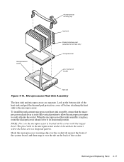
...sink and peel the thermal-pad protective cover off before attaching the heat sink to the microprocessor. To install the replacement microprocessor/heat sink assembly, ensure that the microprocessor release lever is in its fully vertical ...securing clip over the socket tab nearest the front of the system board, and then snap it over the tab on the back of the socket.
Removing and Replacing Parts 4-...
Service Manual - Page 66
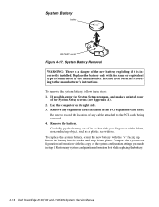
... the manufacturer's instructions. To remove the system battery, follow these steps: 1. If possible, enter the System Setup program, and make a printed copy
of the System Setup screens (see Appendix A). 2. Lay the computer on its right side. 3. Remove any expansion cards installed in the PCI expansion-card slots.
Be sure to record the location of any cables attached to the PCI cards being removed...