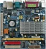
Gigabyte 7CN700ID driver and firmware

Related Gigabyte 7CN700ID Manual Pages
Download the free PDF manual for Gigabyte 7CN700ID and other Gigabyte manuals at ManualOwl.com
Manual - Page 2
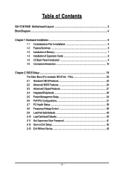
... Standard CMOS Features 22 2-2 Advanced BIOS Features 24 2-3 Advanced Chipset Features 27 2-4 IntegratedPeripherals 30 2-5 Power Management Setup 34 2-6 PnP/PCI Configurations 37 2-7 PC Health Status 38 2-8 Frequency/Voltage Control 39 2-9 Load Fail-Safe Defaults 40 2-10 Load Optimized Defaults 40 2-11 Set Supervisor/User Password 41 2-12 Save & Exit Setup 42 2-13 Exit Without Saving...
Manual - Page 5
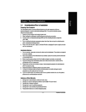
...: 1. Please turn off the computer and unplug its power cord. 2. When handling the motherboard, avoid touching any metal leads or connectors. 3. It is best to wear an electrostatic discharge (ESD) cuff when handling electronic components
(CPU, RAM). 4. Prior to installing the electronic components, please have these items on top of an antistatic pad or
within a electrostatic...
Manual - Page 6
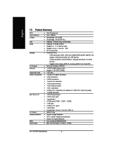
... of 4 IDE devices
- 2 SATA connectors (SATA1/SATA2), allowing connection of 2 SATA
devices
- Supports data striping (RAID 0), mirroring (RAID 1) for Serial ATA
O.S Support
Microsoft Windows 2000/XP
Memory
1 DDRII DIMM memory slots
Supports 1.8V DDRII DIMMs
Expanstion Slots 1 PCI slot
Internal Connectors 1 20-pin ATX power connector
...
Manual - Page 7
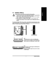
... that the computer
power is switched off to prevent hardware damage. 3. Memory modules have a foolproof insertion design. A memory module can be
installed in only one direction. If you are unable to insert the module, please switch the direction. The motherboard supports DDR II memory modules, whereby BIOS will automatically detect memory capacity and specifications. Memory modules are designed...
Manual - Page 8
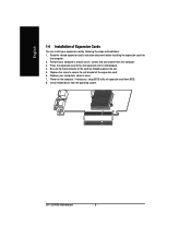
... card firmly into expansion slot in motherboard. 4. Be sure the metal contacts on the card are indeed seated in the slot. 5. Replace the screw to secure the slot bracket of the expansion card. 6. Replace your computer's chassis cover. 7. Power on the computer, if necessary, setup BIOS utility of expansion card from BIOS. 8. Install related driver from the operating system.
GA-7CN700ID Motherboard...
Manual - Page 9
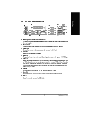
... Serial port.
VGA Port Monitor can be connected to VGA port.
LAN Port The provided Internet connection is fast Ethernet, providing data transfer speeds of 10/100Mbps.
USB port Before you connect your device(s) into USB connector(s), please make sure your device(s) such as USB keyboard, mouse, scanner, zip, speaker...etc. have a standard USB interface. Also make sure your OS supports USB controller...
Manual - Page 11
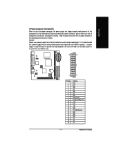
... (2x10 pin ATX )
With the use of the power connector, the power supply can supply enough stable power to all the components on the motherboard. Before connecting the power connector, please make sure that all components and devices are properly installed. Align the power connector with its proper location on the motherboard and connect it tightly. Caution! Please use...
Manual - Page 12
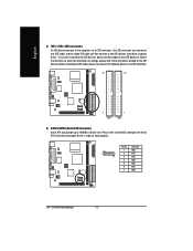
... information on settings, please refer to the instructions located on the IDE device). Before attaching the IDE cable, please take note of the foolproof groove in the IDE connector.
40
39
2 IDE1
1 IDE2
3) SATA1/SATA2 (Serial ATA Connector,) Serial ATA can provide up to 150MB/s transfer rate. Please refer to the BIOS setting for the Serial ATA and install the proper driver in order...
Manual - Page 13
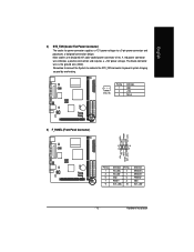
...designed with color-coded power connector wires. A red power connector wire indicates a positive connection and requires a +12V power voltage. The black connector wire is the ground wire (GND). Remember to connect the System fan cable to the SYS_FAN ...
Definition Pin No.
HD_LED+ 2
HD_LED- 4
GND
6
RESET
8
ACT_LED+ 10
Definition MSGLED+ MSGLEDPWRSW GND ACT_LED-
- 13 -
Hardware Installation
Manual - Page 15
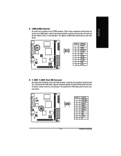
... pin assignment carefully while you connect the front USB cable, incorrect connection between the cable and connector will make the device unable to work or even damage it. For optional front USB cable, please contact your local dealer.
9
1
10
2
Pin No. 1 2 3 4 5 6 7 8 9 10
Definition Power (5V) Power (5V) USB DXUSB DyUSB DX+ USB Dy+ GND GND No Pin NC
- 15 -
Hardware Installation
Manual - Page 16
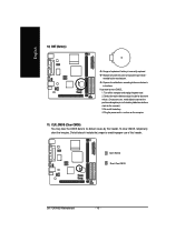
... manufacturer. Dispose of used batteries according to the manufacturer's instructions. If you want to erase CMOS... 1. Turn off the computer and unplug the power cord. 2. Gently take out the battery and put it... the battery holder to makethem short for five seconds.) 3. Re-install the battery. 4. Plug the power cord in and turn on the computer.
11) CLR_CMOS (Clear CMOS) You may clear the CMOS data...
Manual - Page 19
English
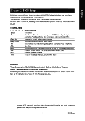
Chapter 2 BIOS Setup
BIOS (Basic Input and Output System) includes a CMOS SETUP utility which allows user to configure required settings or to activate certain system features. The CMOS SETUP saves the configuration in the CMOS SRAM of the motherboard. When the power is turned off, the battery on the motherboard supplies the necessary power to the CMOS SRAM.
CONTROL KEYS Enter...
Manual - Page 23
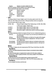
...typically 512K for systems with 512K memory installed on the motherboard, or 640K for systems with 640K or more memory installed on the motherboard.
Extended Memory
The BIOS determines how much extended memory is present during the POST. This is the amount of memory located above 1 MB in the CPU's memory address map.
Total Memory
This item displays the memory size that used.
- 23 -
BIOS Setup
Manual - Page 25
... updated. But flash tools can
update BIOS always.
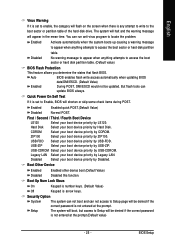
Quick Power On Self Test
If it is set to Enable, BIOS will shorten or skip some check items during POST.
Enabled
Enabled quick POST.(Default Value)
Disabled
Normal POST.
First / Second / Third / Fourth Boot Device
LS120
Select your boot device priority by LS120.
Hard Disk Select your boot device priority by Hard Disk...
Manual - Page 26

English
Video BIOS Shadow
It determines whether video BIOS is able to copy to RAM, however, it isoptional from
chipset design. Video Shadow will increase the video speed.
Enabled
Video shadow is enabled .(Default Value)
Disabled
Video shadow is desibled.
(Note) This item will show up when you install a processor which supports this function.
GA-7CN700ID Motherboard
- 26 -
Manual - Page 31
...key in MAC Address.
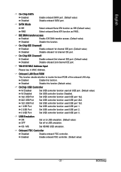
Onboard LAN Boot ROM
This function decide whether to invoke the boot ROM of the onboard LAN chip.
Enabled
Enable this function.
Disabled
Disable this function.(Default value)
OnChip USB Controller
All Enabled
Set USB controller function used all USB port. (Default value)
All Disabled
Set USB controller function Disabled.
1&2 USB Port Set USB controller function used...
Manual - Page 37
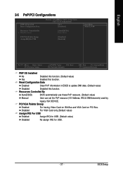
...ESCD & update DMI data. (Default value)
Disabled
Disabled this function.
Resources Controlled By
Auto(ESCD)
BIOS automatically use these PnP rescuers. (Default value)
Manual
User can set the PnP resource (I/O Address, IRQ & DMAchannels) used by
legacy ISA DEVICE.
PCI/VGA Palette Snoop
Enabled
For having Video Card on ISA Bus and VGA Card on PCI Bus.
Disabled
For VGA Card only.(Default...