Gigabyte GA-6LXSG driver and firmware

Related Gigabyte GA-6LXSG Manual Pages
Download the free PDF manual for Gigabyte GA-6LXSG and other Gigabyte manuals at ManualOwl.com
Manual - Page 3
... Trusted Computing (Optional 42 2-2-3 PCI Subsystem Settings 43 2-2-3-1 PCI Express Settings 45 2-2-4 CPU Configuration 47 2-2-5 SATA Configuration 51 2-2-5-1 Software Feature Mask Configuration 53 2-2-6 Info Report Configuration 55 2-2-7 USB Configuration 56 2-2-8 IT8732 Super IO Configuration 57 2-2-9 IT8732 HW Monitor 59 2-2-10 Serial Port Console Redirection 60 2-2-11 Network Stack...
Manual - Page 5
Box Contents
GA-6LXSG/GA-6LXSL motherboard Driver CD Two SATA cables I/O Shield
• The box contents above are for reference only and the actual items shall depend on the product package you obtain. The box contents are subject to change without notice.
• The motherboard image is for reference only.
- 5 -
Manual - Page 7
... BIOS recovery jumper Clear CMOS jumper ME recovery jumper Clearing supervisor password jumper TPM module connector SATA 6Gb/s connectors SATA 6Gb/s connectors SATA 6Gb/s connector SATA 6Gb/s connector SATA port 1 DOM support jumper SATA port 0 DOM support jumper System fan connector#2 System fan connector#1 USB 3.0 header USB 2.0 Type A connector USB 2.0 header Intel H87 Express chipset ME Update...
Manual - Page 11
... a motherboard, CPU or memory. If you do not have an ESD wrist strap, keep your hands dry and first touch a metal object to eliminate static electricity. • Prior to installing the motherboard, please have it on top of an antistatic pad or within an electrostatic shielding container. • Before unplugging the power supply cable from the motherboard, make...
Manual - Page 12
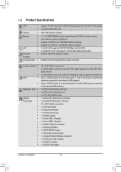
...Gen3 x16 bus) 1 x PCIe x1 slot (Gen2 x1 bus) 2 x PCI 32bit/33MHz slots 1 x 24-pin ATX main power connector 1 x 8-pin ATX 12V power connector 10 x SATA 6Gb/s connectors 1 x CPU fan header 4 x System fan header 1 x Front panel header 1 x PMBus header 1 x Front USB 3.0 header 1 x Front USB 2.0 header 1 x USB 2.0 Type A connector 1 x Serial port header 1 x SATA SGPIO header 1 x Back plane board header...
Manual - Page 13
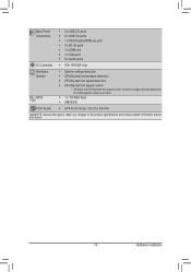
... port ŠŠ 6 x Audio jacks
I/O Controller ŠŠ ITE® IT8732F chip
Hardware Monitor
BIOS
ŠŠ System voltage detection ŠŠ CPU/System temperature detection ŠŠ CPU/System fan speed detection ŠŠ CPU/System fan speed control * Whether the CPU/system fan speed control function is supported will depend on
the CPU/system cooler you install...
Manual - Page 14
... not recommended
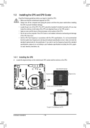
that the system bus frequency be set beyond hardware specifications since it does not meet the standard requirements for the peripherals. If you wish to set the frequency beyond the standard specifications, please do so according to your hardware specifications including the CPU, graphics card, memory, hard drive, etc.
1-3-1 Installing the CPU
A. Locate the alignment keys on...
Manual - Page 15
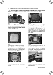
B. Follow the steps below to correctly install the CPU into the motherboard CPU socket.
Before installing the CPU, make sure to turn off the computer and unplug the power cord from the power outlet power plug to prevent any damage to prevent damage to the CPU.
Step 1: Gently press the CPU socket lever handle down and away from the socket with your finger...
Manual - Page 16
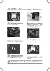
... closely. (Refer to your CPU cooler installation manual for instructions on installing the cooler.)
Step 5:
After the installation, check the back of the motherboard. If the push pin is inserted as the picture above shows, the installation is complete.
Step 6:
Finally, attach the power connector of the CPU cooler to the CPU fan header (CPU_FAN) on the motherboard.
Use extreme care when...
Manual - Page 17
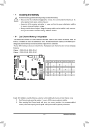
... you begin to install the memory: • Make sure that the motherboard supports the memory. It is recommended that memory of the
same capacity, brand, speed, and chips be used. • Always turn off the computer and unplug the power cord from the power outlet before installing
the memory to prevent hardware damage. • Memory modules have a foolproof design. A memory module can be...
Manual - Page 18
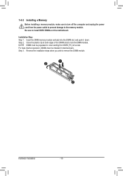
1-4-2 Installing a Memory
Before installing a memory module, make sure to turn off the computer and unplug the power cord from the power outlet to prevent damage to the memory module. Be sure to install DDR3 DIMMs on this motherboard.
Installation Step: Step 1. Insert the DIMM memory module vertically into the DIMM slot, and push it down. Step 2. Close the plastic clip at both edges...
Manual - Page 19
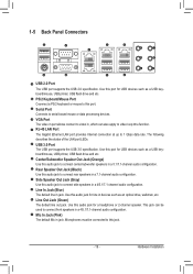
...port for USB devices such as a USB keyboard/mouse, USB printer, USB flash drive and etc.
PS/2 Keyboard/Mouse Port Coonnect a PS/2 keyboard or mouse to this port.
Serial Port Connects to serial-based mouse or data processing devices.
VGA Port The video in port allows connect to video in, which can also apply to video loop thru function. RJ-45 LAN Port The Gigabit Ethernet LAN port provides Internet...
Manual - Page 20
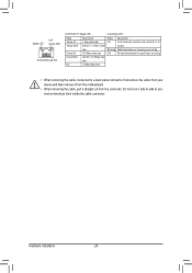
... network or no
access
Blinking Data transmission or receiving is occurring
Off
No data transmission or receiving is occurring
Green Blink Identify 100 Mbps data
rate
Off
10 Mbps data rate
• When removing the cable connected to a back panel connector, first remove the cable from your device and then remove it from the motherboard...
Manual - Page 21
... 25 16
14
13
28
18
34 35
27
31 32 30 33 29
8
2 3
17
9 5
11 12 20
4 10
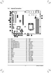
1) ATX1 2) P12V_AUX1 3) CPU0_FAN (CPU Fan) 4) SYS_FAN1 (System Fan) 5) SYS_FAN2 (System Fan) 6) SYS_FAN3 (System Fan) 7) SYS_FAN4 (System Fan) 8) PMBUS 9) SATA0 10) SATA1 11) SATA_2_3 12...) ME_UPDATE 29) CASE_OPEN 30) BIOS_RCVR 31) CLR_CMOS 32) PCH_ME 33) BIOS_PWD 34) SATA_DOM0 35) SATA_DOM1
- 21 -
Hardware Installation
Manual - Page 22
... the connectors you wish to connect. • Before installing the devices, be sure to turn off the devices and your computer. Unplug the
power cord from the power outlet to prevent damage to the devices. • After installing the device and before turning on the computer, make sure the device cable has
been securely attached to the connector on the motherboard.
- 22 -
Hardware...
Manual - Page 48
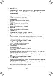
.... CPU C7 state
Display the support information of CPU C7 state feature. Cache Information
L1 Data Cache / L1 Code Cache / L2 Cache / L3 Cache
Displays the technical specifications for the installed processor. Hyper-threading
The Intel Hyper Threading Technology allows a single processor to execute two or more separate threads concurrently. When hyper-threading is enabled, multi-threaded software...
Manual - Page 49
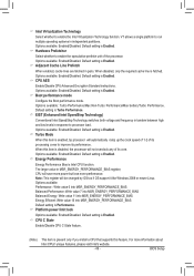
... into MSR_ENERGY_PERFORMANCE_BIAS Default setting is Performance. Platform power limit lock
Options available: Enabled/Disabled. Default setting is Enabled. CPU C State
Enable/Disable CPU C State feature.
(Note)
This item is present only if you install a CPU that supports this feature. For more information about
Intel CPUs' unique features, please visit Intel's website.
- 49 -
BIOS Setup
Manual - Page 52
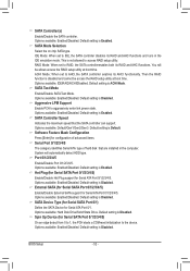
.... Default setting is Enabled. SATA Controller Speed
Indicates the maximum speed that the SATA controller can support. Options available: Default/Gen1/Gen2/Gen3. Default setting is Default. Software Feature Mask Configuration
Press [Enter] for configuration of advanced items. Serial Port 0/1/2/3/4/5
The category identifies Serial ATA type of hard disk that are installed in the computer. System...
Manual - Page 68
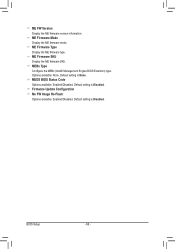
.... ME Firmware SKU Display the ME firmware SKU. MEBx Type Configure the MEBx (Intel® Management Engine BIOS Extention) type . Options available: None. Default setting is None. MEDS BIOS Status Code Options available: Enabled/DIsabled. Default setting is Disabled. Firmware Update Configuration Me FW Image Re-Flash Options available: Enabled/DIsabled. Default setting is Disabled.
BIOS Setup...
Manual - Page 87
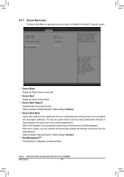
...-signed with valid digital certificates. This way, the system knows all the files being loaded before Windows 8 loads and gets to the login screen have not been tampered with. When set to Standard, it will automatically load the Secure Boot keys form the BIOS databases. When set to Custom, you can customize the Secure Boot settings and manually load its keys...