Gigabyte GA-7PESH3 driver and firmware

Related Gigabyte GA-7PESH3 Manual Pages
Download the free PDF manual for Gigabyte GA-7PESH3 and other Gigabyte manuals at ManualOwl.com
Manual - Page 3
... 19 1-7 Jumper Settings 34
Chapter 2 BIOS Setup 40 2-1 The Main Menu 42 2-2 Advanced Menu 44
2-2-1 PCI Configuration...45 2-2-2 ACPI Settings...46 2-2-3 Trusted Computing (Optional 47 2-2-4 CPU Configuration 48 2-2-4-1 CPU Power Management Configuration 51 2-2-5 Runtime Error Logging 52 2-2-6 SATA Configuration 53 2-2-7 Super IO Configuration 54 2-2-8 Serial Port Console Redirection 56...
Manual - Page 5
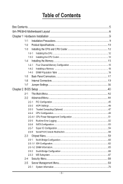
Box Contents
GA-7PESH3 Motherboard Driver CD Two SATA cables I/O Shield CPU Power cables
• The box contents above are for reference only and the actual items shall depend on the product package you obtain. The box contents are subject to change without notice.
• The motherboard image is for reference only.
- 5 -
Manual - Page 8
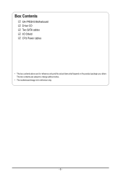
... slot/Running at x8; shared
bandwidth with PCI-E slot 3) PCI-E slot 7 (x16 slot/Running at x16) IPMB connector ASPEED AST2300 BMC firmware readiness LED Force to Stop FRB1 Timer jumper Front audio header S/PDIF Out header PMBus Power Select jumper
CAUTION! If a SATA type hard drive is connected to the motherboard, please ensure the jumper is closed and...
Manual - Page 9
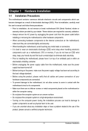
... a motherboard, CPU or memory. If you do not have an ESD wrist strap, keep your hands dry and first touch a metal object to eliminate static electricity. • Prior to installing the motherboard, please have it on top of an antistatic pad or within an electrostatic shielding container. • Before unplugging the power supply cable from the motherboard, make...
Manual - Page 10
... Specifications
CPU
Chipset Memory
LAN
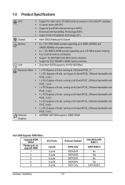
ŠŠ Support for Intel® Xeon® E5-2600 series processors in the LGA2011 package ŠŠ L3 cache varies with CPU ŠŠ Supports QuickPath Interconnect up to 8GT/s ŠŠ Enhanced Intel SpeedStep Technology (EIST) ŠŠ Support Intel Virtualization Technology (VT)
ŠŠ Intel® C602 (Patsburg-A) Chipset...
Manual - Page 11
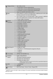
...back plane board header 2 x SAS SGPIO headers 1 x USB 2.0/1.1 header 1 x USB 3.0 header 2 x USB 3.0 Type A connectors 1 x TPM module connector 1 x Front audio header 1 x RAID KEY header 1 x S/PDIF Out header 4 x USB 2.0/1.1 ports 3 x RJ-45 port (1 x 10/100 dedicated management LAN port) 1 x COM port 1 x VGA port
I/O Controller ŠŠ ASPEED® AST2300 BMC chip
Hardware Monitor
BIOS Form...
Manual - Page 12
... not recommended
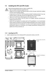
that the system bus frequency be set beyond hardware specifications since it does not meet the standard requirements for the peripherals. If you wish to set the frequency beyond the standard specifications, please do so according to your hardware specifications including the CPU, graphics card, memory, hard drive, etc.
1-3-1 Installing the CPU
A. Locate the alignment keys on...
Manual - Page 13
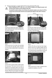
... steps below to correctly install the CPU into the motherboard CPU socket. •• Before installing the CPU, make sure to turn off the computer and unplug the power cord from the power outlet to prevent damage to the CPU.
•• To protect the socket contacts, do not remove the protective plastic cover unless the CPU is inserted into the...
Manual - Page 14
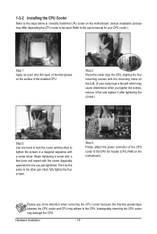
... steps below to correctly install the CPU cooler on the motherboard. (Actual installation process may differ depending the CPU cooler to be used. Refer to the user's manual for your CPU cooler.)
Step 1: Apply an even and thin layer of thermal grease on the surface of the installed CPU.
Step 2: Place the cooler atop the CPU, aligning the four mounting...
Manual - Page 15
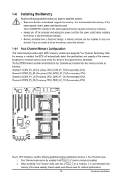
... you begin to install the memory: • Make sure that the motherboard supports the memory. It is recommended that memory of the
same capacity, brand, speed, and chips be used. (Go to GIGABYTE's website for the latest supported memory speeds and memory modules.) • Always turn off the computer and unplug the power cord from the power outlet before installing the memory to prevent hardware...
Manual - Page 16
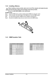
1-4-2 Installing a Memory
Before installing a memory module, make sure to turn off the computer and unplug the power cord from the power outlet to prevent damage to the memory module. Be sure to install DDR3 DIMMs on this motherboard. Installation Step: Step 1. Insert the DIMM memory module vertically into the DIMM slot, and push it down. Step 2. Close the plastic clip at both edges...
Manual - Page 17
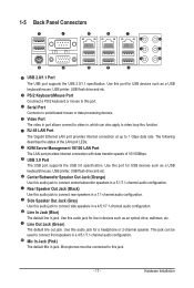
... for USB devices such as a USB keyboard/mouse, USB printer, USB flash drive and etc.
PS/2 Keyboard/Mouse Port Coonnect a PS/2 keyboard or mouse to this port.
Serial Port Connects to serial-based mouse or data processing devices.
Video Port The video in port allows connect to video in, which can also apply to video loop thru function. RJ-45 LAN Port The Gigabit Ethernet LAN port provides Internet...
Manual - Page 18
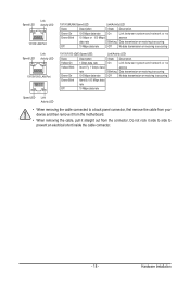
...LAN Port
10/100 (MLAN) Speed LED:
Link/Activity LED:
State Green On Green Blink
Off
Description 100 Mbps data rate 10 Mbps or 100 Mbps data rate 10 Mbps data rate
State Description
On
Link between system and network...system and network or ...cable connected to a back panel connector, first remove the cable from your device and then remove it from the motherboard.
• When removing the cable...
Manual - Page 19
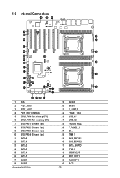
... 17
1) ATX1 2) P12V_AUX1 3) P12V_AUX2 4) PWR_DET1 (PMBus) 5) CPU0_FAN (for primary CPU) 6) CPU1_FAN (for seconary CPU) 7) SYS_FAN1 (System Fan) 8) SYS_FAN2 (System Fan) 9) SYS_FAN3 (System Fan)... 10) SYS_FAN4 (System Fan) 11) SATA0 12) SATA1 13) SATA2 14) SATA3 15) SATA4 16) SATA5 17) SAS01 18) SAS23 Hardware Installation...
Manual - Page 20
... the connectors you wish to connect. • Before installing the devices, be sure to turn off the devices and your computer. Unplug the power
cord from the power outlet to prevent damage to the devices. • After installing the device and before turning on the computer, make sure the device cable has
been securely attached to the connector on the motherboard.
- 20 -
Hardware...
Manual - Page 21
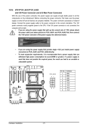
... on the motherboard. Before connecting the power connector, first make sure the power supply is turned off and all devices are properly installed. The power connector possesses a foolproof design. Connect the power supply cable to the power connector in the correct orientation. The 12V power connector mainly supplies power to the CPU. If the 12V power connector is not connected, the computer will...
Manual - Page 22
ATX
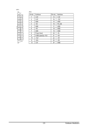
ATX1
13 1
ATX1 Pin No. Definition
Pin No. Definition
1 3.3V
13 3.3V
2 3.3V
14 -12V
3 GND
15 GND
4 +5V
16 PS_ON
5 GND
17 GND
6 +5V
18 GND
7 GND
19 GND
8 Power Good
20 -5V
9 5VSB (stand by +5V)
21 +5V
10 +12V
22 +5V
12 24
11 +12V 12 3.3V
23 +5V 24 GND
ATX_12V
FDD
IDE
- 22 -
Hardware Installation
Manual - Page 23
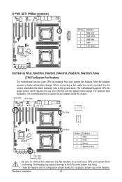
... wire). The motherboard supports CPU fan speed control, which requires the use of a CPU fan with fan speed control design. For optimum heat dissipation, it is recommended that a system fan be installed inside the chassis.
SYS_FAN3 SYS_FAN4
1
CPU1_FAN
CPU0_FAN
1
Pin No. 1 2 3 4
Definition GND +12V Sense Speed Control
SYS_FAN1 SYS_FAN2
• Be sure to connect fan cables to the fan...
Manual - Page 32
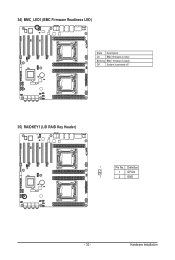
34) BMC_LED1 (BMC Firmware Readiness LED)
State Description
On
BMC firmware is initial
Blinking BMC firmware is ready
Off
System is powered off
35) RAIDKEY1 (LSI RAID Key Header)
1
Pin No. Definition
1 GPIO4
2
2 GND
- 32 -
Hardware Installation
Manual - Page 50
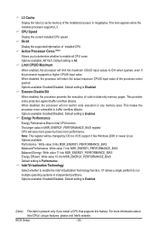
... the total L2 cache memory of the installed processor in megabytes. This item appears when the installed processor supports L3 . CPU Speed
Display the current installed CPU speed. 64-bit
Display the supported infprmation of installed CPU. Active Processor Cores (Note)
Allows you to determine whether to enable all CPU cores. Options available: All/1/2/3. Default setting is All. Limit CPUID Maximum...